7 Pin Ignition Module Dodge Ram Ignition Switch Wiring Diagram
So, you're diving into the ignition system of your Dodge Ram? Excellent! Understanding the 7-pin ignition module wiring diagram is crucial whether you're troubleshooting a no-start condition, upgrading your security system, or simply expanding your automotive knowledge. This isn't a job for beginners, but with a little guidance and respect for electrical systems, you can confidently tackle this project.
Why You Need This Diagram
The ignition system is the heart of your truck. Without it, you're going nowhere. A reliable wiring diagram is essential for:
- Troubleshooting: Pinpointing faulty wiring, shorts, or opens in the ignition circuit.
- Repairs: Replacing damaged components like the ignition switch, module, or wiring harness.
- Upgrades: Installing aftermarket security systems, remote starters, or performance ignition components.
- Understanding: Gaining a deeper understanding of how your Dodge Ram's electrical system functions.
Without a proper diagram, you're essentially poking around in the dark, which can lead to further damage and frustration. This particular diagram focuses on the 7-pin ignition module, commonly found in older Dodge Ram models (typically late 80s to mid-90s), although the specific years and models can vary, so *always* verify your vehicle's specific diagram.
Key Specs and Main Parts
Before we dive into the diagram itself, let's define the key components involved:
- Ignition Switch: This is where it all starts. When you turn the key, the ignition switch sends power to various circuits, including the ignition module. It has several positions: OFF, ACC (Accessory), ON (Run), and START.
- Ignition Module (also known as the Engine Control Module Driver): This is the brain of the ignition system. It receives signals from the crankshaft position sensor (CKP) and the ignition switch and controls the firing of the ignition coil(s). It ensures the spark plugs fire at the correct time. 7-pin configurations are common in older distributor-based ignition systems.
- Ignition Coil: A transformer that steps up the battery's voltage (12V) to a very high voltage (thousands of volts) needed to create a spark at the spark plugs.
- Crankshaft Position Sensor (CKP): Provides the engine control module (ECM) or ignition module with information about the crankshaft's position and speed. This is critical for timing the spark correctly.
- Wiring Harness: A bundle of wires that connects all the components. Each wire has a specific function and is often color-coded.
- Battery: The source of electrical power for the entire system.
The 7 pins on the ignition module typically correspond to the following functions (though variations may exist, so always refer to your specific diagram):
- Battery Voltage (+12V)
- Ground
- Crankshaft Position Sensor (CKP) Signal
- Ignition Coil Driver (to coil negative terminal)
- Start Signal (from ignition switch)
- Run Signal (from ignition switch)
- Diagnostic Signal (to diagnostic connector, sometimes not used)
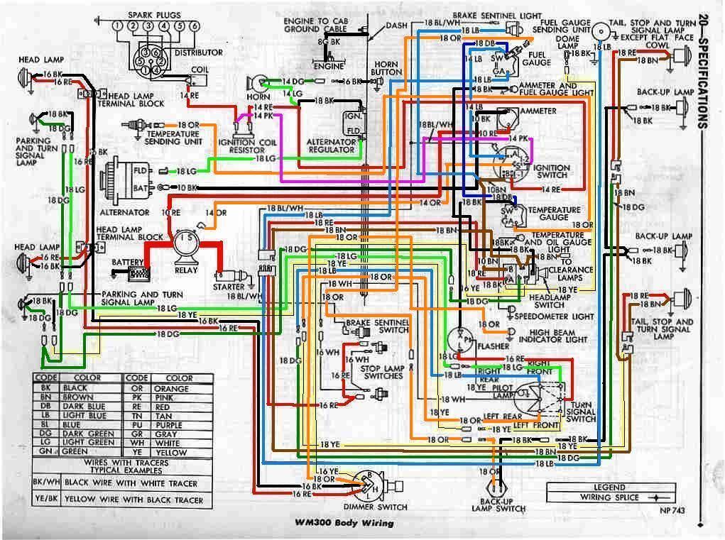
Understanding the Symbols
Wiring diagrams use a standardized set of symbols. Understanding these symbols is crucial for interpreting the diagram correctly.
- Solid Lines: Represent wires. The thickness of the line doesn't necessarily indicate wire gauge.
- Dashed Lines: Often indicate shielded wires or wires that are part of a harness.
- Color Codes: Each wire is typically assigned a color. The diagram will have a legend indicating which color corresponds to which function. Common colors include Red (power), Black (ground), and various other colors for signals.
- Circles: Represent connectors or splices.
- Rectangles: Represent components like switches, relays, or sensors.
- Ground Symbol: Looks like a series of descending lines. Indicates a connection to the vehicle's chassis ground.
- Numbers and Letters: Used to identify specific wires, terminals, or components.
Important: The color codes on the diagram *should* match the actual wire colors in your vehicle. However, always double-check with a multimeter to confirm the function of each wire.
How It Works: A Simplified Explanation
Here's a simplified overview of how the ignition system works:
- When you turn the ignition key to the START position, the ignition switch sends a signal to the starter solenoid, which engages the starter motor to crank the engine. Simultaneously, the ignition switch sends a "Start" signal to the ignition module.
- Once the engine is running (key in the ON/RUN position), the ignition switch sends a "Run" signal to the ignition module.
- The Crankshaft Position Sensor (CKP) sends a signal to the ignition module indicating the crankshaft's position.
- Based on the CKP signal and the engine's timing requirements, the ignition module sends a signal to the ignition coil.
- The ignition coil steps up the voltage and sends it to the distributor (if equipped), which distributes the high-voltage spark to the correct spark plug at the correct time.
- The spark plug ignites the air-fuel mixture in the cylinder, causing combustion.
The 7-pin ignition module acts as a sophisticated electronic switch, precisely controlling when the ignition coil discharges its high-voltage spark. By knowing the crankshaft position, it ensures optimal timing for efficient combustion.
Real-World Use: Basic Troubleshooting Tips
Here are a few troubleshooting tips based on the wiring diagram:
- No Spark: Check for voltage at the ignition coil positive terminal with the key in the ON position. If no voltage, trace the wiring back to the ignition switch and battery. Check the ignition module's power and ground connections.
- Intermittent Spark: Could be a loose connection in the wiring harness or a faulty CKP sensor. Use a multimeter to check for continuity and voltage drops in the wiring.
- Engine Cranks But Doesn't Start: Check the "Start" signal from the ignition switch to the ignition module. Also, verify the CKP sensor signal is present while cranking.
Always use a multimeter to verify voltage, continuity, and ground. A test light can be helpful, but a multimeter provides more accurate readings.
Safety First!
Working with automotive electrical systems can be dangerous. Here are some essential safety precautions:
- Disconnect the Battery: Always disconnect the negative battery cable before working on any electrical components. This prevents accidental shorts and potential shocks.
- High Voltage: The ignition coil produces extremely high voltage. Avoid touching the ignition coil or spark plug wires while the engine is running or being cranked.
- Fuses: If a fuse blows, replace it with a fuse of the *same amperage*. Using a higher amperage fuse can damage the wiring and components.
- Proper Tools: Use insulated tools to prevent shorts.
Remember the ignition coil can store a charge even after the battery is disconnected. Discharge the coil before handling it by grounding the coil's positive terminal (after disconnecting from the battery and module, of course!).
Get Your Diagram!
Now that you understand the basics, you'll need the actual wiring diagram for *your specific* Dodge Ram model and year. Using the wrong diagram can lead to misdiagnosis and further problems.
We have the file. Download the diagram to delve deeper into the intricacies of your vehicle's ignition system, but always double-check against reliable online resources to verify compatibility.
With the right knowledge, tools, and precautions, you can confidently diagnose and repair your Dodge Ram's ignition system. Good luck, and stay safe!