
7 Pin To 4 Pin Trailer Wiring Adapter
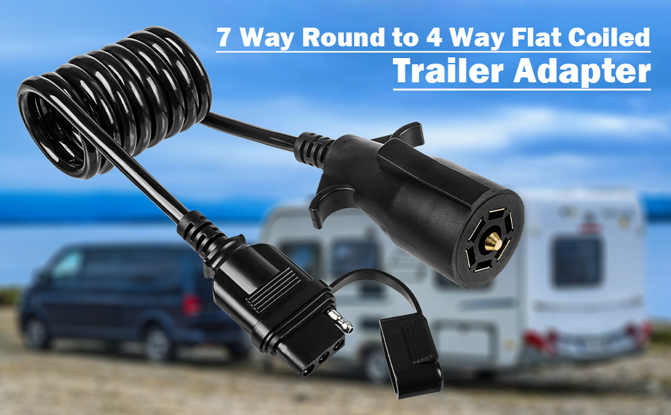
Let's talk about 7-pin to 4-pin trailer wiring adapters. Understanding how these little devices work is crucial for anyone who regularly tows a trailer, especially if you're dealing with different types of vehicles or trailers that have incompatible wiring setups. This article provides a deep dive into the technical aspects of these adapters, allowing you to troubleshoot issues, perform repairs, and understand the underlying principles.
Purpose and Importance
The primary purpose of a 7-pin to 4-pin trailer wiring adapter is to bridge the gap between vehicles equipped with a 7-pin trailer connector (commonly found on newer trucks and SUVs, and often referred to as an "RV blade" connector) and trailers utilizing a 4-pin flat connector (more prevalent on smaller trailers, boat trailers, and utility trailers). This adaptation is necessary because the 7-pin connector carries more signals than the 4-pin, providing features like reverse lights, electric brakes, and auxiliary power, in addition to the standard lighting functions. Without the adapter, you wouldn't be able to properly connect and operate the trailer's lights, potentially leading to safety hazards and legal issues.
Understanding this adapter is essential for several reasons:
- Repairs and Troubleshooting: Identifying a faulty adapter is a common step in diagnosing trailer lighting problems.
- Custom Installations: If you're upgrading a trailer's wiring or adding functionality like electric brakes, understanding the adapter's role is vital.
- Safety: Ensuring correct wiring prevents electrical shorts, blown fuses, and malfunctioning lights, all crucial for safe towing.
- Legal Compliance: Trailer lighting is subject to regulations. A properly functioning adapter ensures you meet those standards.
Key Specs and Main Parts
The adapter itself is relatively simple, but understanding its components and specifications is key:
- 7-Pin Connector (Vehicle Side): This end plugs into the 7-pin trailer connector on your vehicle. It follows the SAE J560 standard, which defines the pin assignments.
- 4-Pin Connector (Trailer Side): This end connects to the 4-pin flat connector on your trailer.
- Wiring Harness: The internal wiring connects the corresponding pins between the two connectors. The quality of the wiring (gauge and insulation) is important for reliability and preventing voltage drop.
- Housing: The adapter's housing protects the internal wiring from the elements and physical damage. Look for weatherproof designs.
Here are some key specifications to consider:
- Voltage Rating: Typically 12V DC, which is the standard voltage for automotive electrical systems.
- Current Capacity: While the adapter itself doesn't draw current, it must be able to handle the combined current draw of all the trailer's lights. A high-quality adapter will specify its maximum current capacity.
- Weather Resistance: IP ratings (e.g., IP65) indicate the level of protection against dust and water ingress.
Symbols and Wiring Diagram Conventions
Let's break down the common symbols you'll encounter in a 7-pin to 4-pin trailer wiring diagram:
- Lines: Represent wires. Thicker lines may indicate wires with a larger gauge (capable of carrying more current).
- Colors: Each wire is color-coded to indicate its function. The standard color codes for both 7-pin and 4-pin connectors are as follows (but always verify with your specific trailer):
- 4-Pin:
- White: Ground
- Brown: Tail Lights
- Yellow: Left Turn/Brake
- Green: Right Turn/Brake
- 7-Pin (Typical):
- White: Ground
- Brown: Tail Lights
- Yellow: Left Turn/Brake
- Green: Right Turn/Brake
- Blue: Electric Brakes
- Black: 12V+ Auxiliary Power
- Purple: Reverse Lights
- 4-Pin:
- Circles or Dots: Represent connection points where wires are joined.
- Rectangles or Squares: May represent fuses or relays (though rarely found within the adapter itself, these might be in the vehicle's wiring).
In the diagram, you'll see lines connecting the pins on the 7-pin connector to the corresponding pins on the 4-pin connector. The following mapping is crucial:
- 7-Pin White (Ground) -> 4-Pin White (Ground)
- 7-Pin Brown (Tail Lights) -> 4-Pin Brown (Tail Lights)
- 7-Pin Yellow (Left Turn/Brake) -> 4-Pin Yellow (Left Turn/Brake)
- 7-Pin Green (Right Turn/Brake) -> 4-Pin Green (Right Turn/Brake)
- 7-Pin Blue (Electric Brakes) -> Not Connected (This function is lost with a 4-pin trailer)
- 7-Pin Black (12V+ Auxiliary Power) -> Not Connected (This function is lost with a 4-pin trailer)
- 7-Pin Purple (Reverse Lights) -> Not Connected (This function is lost with a 4-pin trailer)
How It Works
The adapter is fundamentally a passive device. It doesn't contain any active components like relays or microcontrollers. It simply re-routes the signals from the 7-pin connector to the appropriate pins on the 4-pin connector. Because the 4-pin connector only supports basic lighting functions, the adapter leaves the electric brake, auxiliary power, and reverse light signals unconnected. The adapter's internal wiring provides a direct electrical connection between the pins, ensuring that when the vehicle sends a signal (e.g., turn signal), it's carried through the adapter to the trailer lights.
Real-World Use and Basic Troubleshooting
Here are some common troubleshooting tips when dealing with trailer lighting issues:
- No Lights at All: Check the ground connection (white wire) on both the vehicle and the trailer. A poor ground is the most common cause of lighting problems. Also, inspect the vehicle's trailer tow fuse(s).
- One Light Not Working: Verify the bulb itself is good. Then, check the wiring connections for that specific light, both at the adapter and on the trailer. Use a multimeter to test for voltage at the trailer connector.
- Dim Lights: Indicates a voltage drop, often caused by corrosion in the connectors or undersized wiring. Clean the connectors with electrical contact cleaner.
- Blown Fuses: Suggests a short circuit. Inspect the wiring for any damage or exposed wires. Disconnect the trailer and see if the vehicle's lights work normally to isolate the problem to the trailer.
- Erratic Behavior: Can be due to a faulty ground or corrosion in the connectors. Clean and tighten all connections.
Testing the Adapter: You can use a multimeter to check the continuity between the corresponding pins on the 7-pin and 4-pin connectors. If there's no continuity, the adapter is faulty and needs to be replaced.
Safety Considerations
While the adapter itself isn't particularly dangerous, working with automotive electrical systems requires caution:
- Battery Disconnect: Disconnect the negative terminal of the vehicle's battery before working on any wiring to prevent accidental shorts.
- Wiring Damage: Be careful not to damage any wires when installing or removing the adapter. Damaged wiring can create short circuits and fire hazards.
- Fuse Protection: Always use the correct fuse rating for the trailer lighting circuit. Over-fusing can lead to overheating and fires.
- Water Intrusion: Keep the adapter and connectors clean and dry to prevent corrosion. Use dielectric grease on the connector pins to help prevent corrosion.
- Electric Brakes: Remember that using this adapter means you will NOT have electric brake functionality for trailers equipped with them. This is a HUGE safety concern if your trailer requires electric brakes. Ensure your vehicle and trailer are appropriately matched.
Remember that bypassing safety systems like electric brakes can have serious consequences. Always prioritize safety when towing.
We have a detailed wiring diagram available for download. It provides a visual representation of the pin assignments and wiring connections discussed in this article.