
7 Pin Trailer Wiring Diagram With Brakes
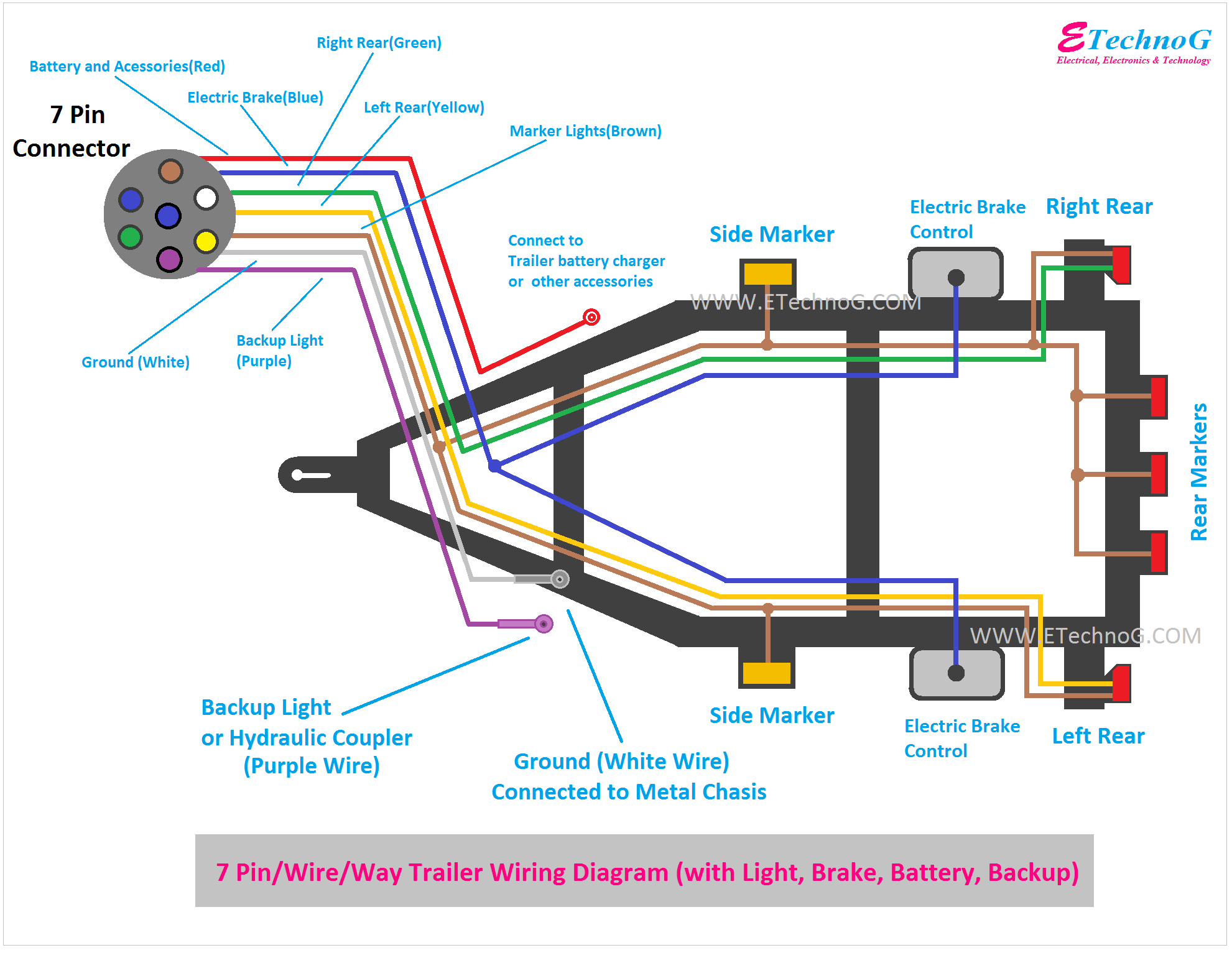
If you're looking to tow a trailer with electric brakes, understanding the 7-pin trailer wiring diagram is absolutely essential. Whether you're troubleshooting existing wiring, installing a new trailer brake controller, or simply want to expand your knowledge of automotive electrical systems, this guide will provide you with the necessary information to confidently tackle the task. We'll cover the purpose of each pin, interpret the diagram symbols, explain how the system functions, and offer practical troubleshooting tips. We even have a downloadable diagram available for your convenience.
Why This Diagram Matters
The 7-pin connector is the backbone of safe and reliable trailer towing when electric brakes are involved. Without a properly wired connector, your trailer brakes won't function correctly, creating a serious safety hazard. A solid understanding of the wiring diagram allows you to:
- Diagnose and repair faulty wiring issues affecting lights, brakes, and auxiliary functions.
- Install a new trailer brake controller or upgrade your existing wiring setup.
- Ensure that your trailer complies with safety regulations.
- Confidently connect your trailer knowing everything is wired correctly.
- Customize your trailer wiring for specific needs, such as adding a backup camera or auxiliary power.
Key Specs and Main Parts
The 7-pin connector provides connections for various functions related to trailer operation. Understanding what each pin controls is the key to understanding the whole system. The main parts involved are:
- 7-Pin Connector (Vehicle Side): This connector is typically mounted near the hitch on your tow vehicle. It's the source of power and control signals for the trailer.
- 7-Pin Connector (Trailer Side): This connector is attached to the trailer wiring harness and plugs into the vehicle-side connector.
- Trailer Brake Controller: Located in the tow vehicle, this device allows the driver to manually or automatically apply the trailer brakes. It's the critical component for controlling the electric brakes.
- Electric Brakes: These are mounted inside the trailer's brake drums or rotors and are activated by the electric current supplied by the brake controller.
- Wiring Harness: The collection of wires that connect the various components, often color-coded for easy identification. The gauge (thickness) of the wire is important, especially for the brake wire, to handle the current.
- Fuses and Circuit Breakers: These protect the electrical system from overloads and short circuits.
Here's a breakdown of the common 7-pin connector functions:
- Pin 1: Ground (White) - Provides a return path for all electrical circuits.
- Pin 2: Tail Lights (Brown) - Powers the trailer's tail lights, side marker lights, and license plate light.
- Pin 3: Left Turn/Stop (Yellow) - Powers the left turn signal and brake light on the trailer.
- Pin 4: Right Turn/Stop (Green) - Powers the right turn signal and brake light on the trailer.
- Pin 5: Electric Brakes (Blue) - Supplies power to the trailer's electric brakes, controlled by the brake controller. This is the most critical wire for safety.
- Pin 6: Auxiliary Power (Red or Black) - Provides a constant 12V power supply for accessories like interior lights or a trailer battery charger. Often fused separately.
- Pin 7: Reverse Lights (Black or Purple) - Powers the trailer's reverse lights.
Symbols: Lines, Colors, and Icons
Understanding the symbols on a wiring diagram is essential for accurate interpretation. Here's a breakdown:
- Lines: Represent wires. The thickness of the line can sometimes, but not always, indicate the wire gauge.
- Colors: Each wire is typically color-coded to match the function (see the pin descriptions above). Consistent color-coding makes troubleshooting much easier.
- Circles: Often represent connection points or splices in the wiring.
- Rectangles: Can represent components like fuses, relays, or the brake controller itself.
- Ground Symbol: A series of lines decreasing in length, indicating a connection to the vehicle's chassis or frame for grounding.
- Light Bulb Symbol: Represents the trailer's lights.
- Brake Symbol: A stylized representation of a brake assembly, often indicating the electric brakes.
Beyond these basic symbols, manufacturers may use slightly different icons on their specific diagrams. Always refer to the diagram's legend or key for clarification.
How It Works
The 7-pin trailer wiring system works by providing a standardized interface for transmitting electrical signals from the tow vehicle to the trailer. Here's a breakdown of the process:
- Basic Lighting: When you activate your vehicle's lights (headlights, tail lights, turn signals, brake lights), the corresponding circuits in the tow vehicle send power through the 7-pin connector to the trailer lights.
- Electric Brakes: When you press the brake pedal, the brake controller senses the deceleration and sends a proportional amount of current through the blue wire to the trailer's electric brakes. The harder you brake, the more current is sent, resulting in stronger braking force on the trailer. Some brake controllers use an inertia sensor to measure deceleration, while others use a manual gain setting to adjust the braking force.
- Auxiliary Power: The auxiliary power wire (red or black) provides a constant 12V supply to the trailer, even when the vehicle is off (if properly wired on the vehicle side). This is useful for powering interior lights, charging a trailer battery, or running other accessories. Care must be taken to avoid draining the tow vehicle's battery.
The brake controller is the heart of the braking system. It requires proper installation and calibration to ensure smooth and safe braking performance. It typically requires connections to the vehicle's battery, brake light switch, and the blue wire leading to the trailer connector.
Real-World Use: Basic Troubleshooting Tips
Here are some common troubleshooting tips for 7-pin trailer wiring:
- No Lights: Check the fuses in your tow vehicle and on the trailer. Use a circuit tester to verify that power is reaching the connector. Inspect the ground connection for corrosion or looseness.
- One Light Not Working: Check the bulb first. Then, trace the wiring back to the connector, looking for breaks or loose connections. Test the connector pins with a multimeter to confirm the signal is present.
- Brakes Not Working: Verify that the brake controller is properly connected and calibrated. Check the blue wire for continuity between the tow vehicle and the trailer. Inspect the brake magnets inside the trailer's brake drums for wear or damage. A common issue is a broken or corroded wire within the trailer's brake assembly.
- Erratic Braking: Could indicate a problem with the brake controller, the wiring, or the brake magnets. Try adjusting the brake controller's gain setting. Check for loose connections or corrosion in the brake wiring.
- Use a Multimeter: A multimeter is essential for diagnosing electrical problems. Use it to check for voltage, continuity, and resistance.
Safety: Highlight Risky Components
Working with electrical systems can be dangerous. Here are some safety precautions to keep in mind:
- Disconnect the Battery: Before working on any electrical wiring, disconnect the negative terminal of the tow vehicle's battery to prevent accidental shorts.
- Use Proper Tools: Use insulated tools designed for electrical work.
- Wear Safety Glasses: Protect your eyes from sparks and debris.
- Never Work on a Live Circuit: Always double-check that the circuit is de-energized before working on it.
- Fuses and Circuit Breakers: Always replace fuses with the correct amperage rating. Using a higher amperage fuse can overload the wiring and cause a fire.
- Brake Controller Installation: Follow the manufacturer's instructions carefully when installing a brake controller. Improper installation can lead to brake failure.
- Trailer Brakes: Faulty trailer brakes are a serious safety hazard. Regularly inspect and maintain your trailer's brakes.
Specifically, the electric brake wiring (the blue wire) is critical. It carries significant current, and a short circuit in this wire can overheat the wiring and potentially cause a fire. Always use the correct gauge wire for the brake circuit and ensure that all connections are secure and properly insulated.
We have a detailed 7-pin trailer wiring diagram available for download. It includes color codes, pin assignments, and troubleshooting tips. This diagram will be an invaluable resource for all your trailer wiring needs.
With a little patience and the right knowledge, you can confidently tackle trailer wiring projects and ensure the safe and reliable operation of your trailer. Remember to always prioritize safety and consult a qualified mechanic if you're unsure about any aspect of the work.