
7 Pin Trailer Wiring Harness Extension
Alright, let's talk about 7-pin trailer wiring harness extensions. This isn't rocket science, but understanding the ins and outs can save you a ton of headaches (and money) when towing. Whether you're replacing a damaged harness, extending it for a better fit, or even just deepening your understanding of your vehicle's electrical system, knowing how this works is crucial.
Purpose of Understanding 7-Pin Trailer Wiring Harness Extensions
Why bother learning about this? Simple. Problems with your trailer lights, brakes, or auxiliary power can quickly turn a road trip into a nightmare. Being able to diagnose and fix wiring issues yourself, or at least understand what a mechanic is doing, gives you control and saves you time and money. Plus, correctly extending a harness avoids shorts, blown fuses, and, in extreme cases, electrical fires. This knowledge is invaluable for repairs, upgrades, and general maintenance.
Key Specs and Main Parts
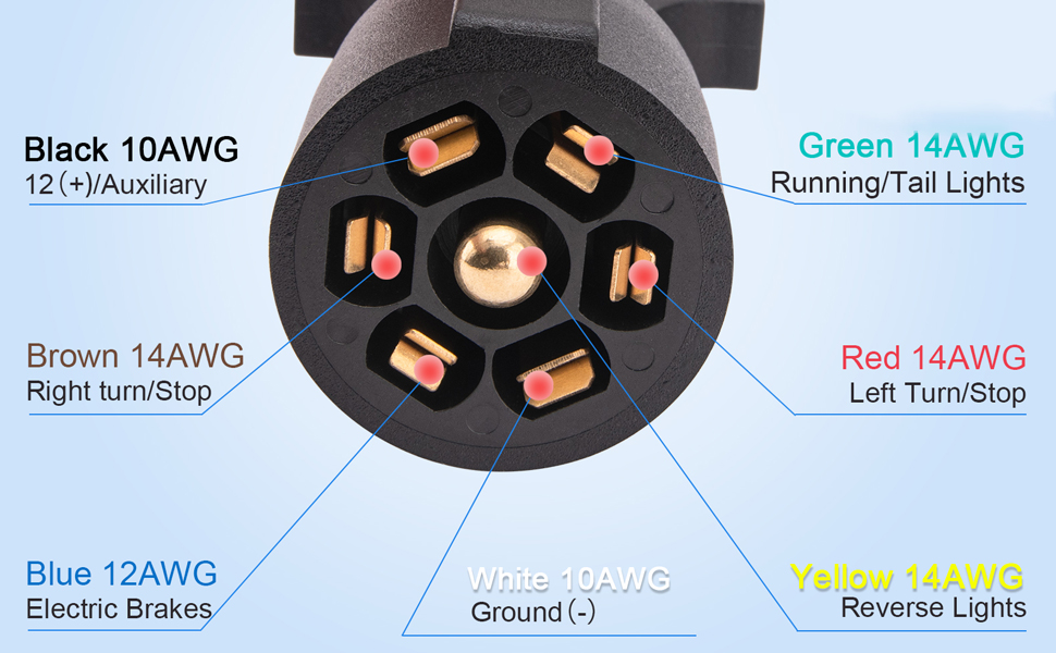
The 7-pin connector is the most common type for towing larger trailers that require more than just basic lighting. These connectors typically handle running lights, turn signals, brake lights, electric trailer brakes, a 12V auxiliary power line, and a ground connection. Here’s a breakdown of the key specs and parts:
- 7-Pin Connector (Vehicle Side): This is the connector mounted on your tow vehicle. It's wired to your vehicle's electrical system, typically tapping into existing lighting circuits and a dedicated brake controller (if you have electric trailer brakes).
- 7-Pin Connector (Trailer Side): This mates with the vehicle-side connector and is wired to the trailer's lighting, brakes, and other electrical components.
- Wiring Harness Extension: This is the crucial part – a length of multi-conductor wire with 7-pin connectors on either end. The gauge (thickness) of the wire is critical; it must be sufficient to handle the current draw of the circuits it serves. Using too thin a wire can lead to voltage drop, overheating, and potential fire hazards. Look for extensions specifically designed for trailer wiring; they are usually made with weather-resistant sheathing to withstand the elements.
- Wire Gauges and Ampacity: Wire gauge is measured using the American Wire Gauge (AWG) system. Lower AWG numbers indicate thicker wires and higher ampacity (current-carrying capacity). For trailer wiring, you'll typically see 10-gauge, 12-gauge, 14-gauge, and 16-gauge wire. 10-gauge is often used for the 12V auxiliary power and electric brake circuits, while smaller gauges are used for lighting. Ampacity is the maximum amount of continuous current a conductor can carry before exceeding its temperature rating. Refer to a wire gauge chart to ensure your wiring is adequate for the intended load.
- Junction Boxes (Optional): In some cases, especially when customizing or heavily modifying a trailer's wiring, you might use junction boxes to create secure and organized connections. These protect the connections from the elements and prevent accidental disconnections.
- Heat Shrink Tubing and Connectors: For extending or repairing wiring, use quality heat shrink tubing and connectors. These provide waterproof and secure connections. Crimp connectors are common, but soldering and using heat shrink is the preferred method for the most robust connections.
Symbols and Color Codes (Important!)
Understanding the color codes and symbols is paramount to wiring your trailer correctly. While there's no *universal* standard, here's a common configuration. Always verify with your trailer and vehicle's documentation.
- White: Ground (GND) - This is your return path for all circuits. A good, clean ground is essential for proper operation. A loose or corroded ground is often the culprit behind flickering lights or other electrical problems.
- Yellow: Left Turn/Brake Light - Combines both functions on the left side of the trailer.
- Green: Right Turn/Brake Light - Combines both functions on the right side of the trailer.
- Brown: Tail/Running Lights - Illuminates the tail lights and side marker lights when your headlights are on.
- Blue: Electric Brake Controller - Sends a signal to the trailer's electric brakes, proportional to the braking force applied in the tow vehicle. Requires a brake controller in the tow vehicle.
- Red: Stop Lamp (Some configurations) or Auxiliary Power - Some use Red for a second stop lamp feed for trailers with complicated lighting.
- Black: 12V Auxiliary Power - Provides a constant 12V power supply to the trailer, often used for charging batteries or powering interior lights. This line is typically fused at the tow vehicle's battery.
When looking at wiring diagrams, you'll typically see solid lines representing wires. Different colors are used to represent different circuits, as described above. Icons might be used to represent specific components, such as a light bulb, a brake actuator, or a battery. A zigzag line often indicates a resistor.
How It Works
The 7-pin connector acts as a central hub, distributing electrical power and signals from the tow vehicle to the trailer. When you activate your turn signals, the corresponding signal is sent through the appropriate wire to the trailer lights. When you press the brake pedal, the brake signal is sent to both the brake lights and, if equipped, the electric brake controller. The auxiliary power line provides a constant 12V supply for various trailer functions.
The key is that each pin in the connector corresponds to a specific function. The extension harness simply extends these connections, maintaining the same functionality at the trailer end as at the vehicle end. Proper wiring ensures that each function operates correctly and safely.
Real-World Use – Basic Troubleshooting Tips
Here are some common problems and how to troubleshoot them:
- No Lights: Start by checking the ground connection. Make sure it's clean, tight, and free of corrosion. Then, check the fuses in your tow vehicle. A blown fuse is a common culprit. Use a multimeter to test for voltage at the connector pins.
- Flickering Lights: This often indicates a loose connection or a corroded ground. Inspect all connections and grounds carefully.
- Brakes Not Working: Check the connection to the brake controller in your tow vehicle. Verify that the brake controller is functioning correctly. Use a multimeter to test for voltage at the brake pin on the trailer connector when the brake pedal is pressed. Inspect the trailer brake magnets.
- Auxiliary Power Not Working: Check the fuse on the auxiliary power line in your tow vehicle. Verify that the battery on the trailer is charging (if applicable).
If you're experiencing persistent problems, it's often helpful to use a test light or multimeter to trace the wiring and identify the source of the issue.
Safety – Highlight Risky Components
Working with electrical systems always carries risks. Here's what to watch out for:
- Battery: Disconnect the trailer battery before working on the wiring to avoid short circuits and potential shocks.
- Wiring Shorts: A short circuit can cause significant damage and even start a fire. Be extremely careful when working with live wires. Always disconnect the power source before making any connections. Use proper insulation and heat shrink tubing to prevent shorts.
- Incorrect Wiring: Wiring the connector incorrectly can damage your vehicle's electrical system or the trailer's components. Double-check your wiring against a reliable diagram before connecting the trailer.
- Overloading Circuits: Ensure that the wire gauge is adequate for the current draw of the circuit. Overloading a circuit can cause the wires to overheat and melt, leading to a fire hazard.
Always disconnect the tow vehicle's battery negative terminal before undertaking significant wiring work.
Trailer brakes can be particularly sensitive. The brake controller signal is a PWM (Pulse Width Modulation) signal. Attempting to measure it with some older multimeters may not give you accurate readings. Consult your brake controller's documentation for specific testing procedures.
Extending your trailer wiring harness can be a straightforward project with the right knowledge and tools. By understanding the purpose, components, wiring diagrams, and safety precautions, you can ensure a safe and reliable connection between your tow vehicle and trailer.
We have a detailed wiring diagram file available for download. Contact us for access, and get ready to wire up your trailer with confidence!