7 Pin Trailer Wiring Harness Port On Camper
For the experienced DIYer looking to understand or troubleshoot their camper's electrical system, the 7-pin trailer wiring harness is a critical component. This article serves as a comprehensive guide to understanding its function, troubleshooting common issues, and ensuring safe operation. Having a firm grasp of this system allows you to perform repairs, diagnose faults, and even customize your camper's electrical setup with confidence. We will provide a downloadable wiring diagram to further aid in your understanding and work.
Purpose of the 7-Pin Trailer Wiring Harness
The 7-pin trailer wiring harness acts as the umbilical cord between your tow vehicle and your camper. It provides the necessary electrical connections to power essential functions on the trailer, including:
- Running lights (tail lights, side marker lights)
- Brake lights and turn signals
- Electric brakes (if equipped)
- Auxiliary power (for charging the camper battery or running appliances)
- Reverse lights
Without a properly functioning 7-pin connector, you'll be without essential safety features, potentially violating traffic laws, and unable to enjoy the full functionality of your camper.
Key Specs and Main Parts
The 7-pin connector, also known as the 7-way connector, adheres to the SAE J560 standard, ensuring compatibility across different vehicle and trailer manufacturers. The standard defines the function of each pin, simplifying troubleshooting and ensuring interchangeability. The key components involved are:
- Tow Vehicle Connector: This is the female receptacle, usually mounted on the tow vehicle's hitch.
- Trailer Connector: This is the male plug that connects to the tow vehicle's receptacle.
- Wiring Harness: The bundle of color-coded wires running between the connector and the trailer's electrical system.
Typical wire gauge ranges from 10-14 AWG (American Wire Gauge) for functions like the auxiliary power and electric brakes, which require higher current carrying capacity, down to 16-18 AWG for lighting circuits. Using the correct gauge wire is crucial to prevent overheating and voltage drop.
The 7-pin connector is weather-resistant, designed to withstand the elements. However, corrosion and damage are common issues, especially in harsh environments.
Symbols and Wiring Diagram Explanation
Understanding the wiring diagram is crucial for diagnosing and repairing electrical problems. Let's break down the key symbols and conventions:
- Lines: Solid lines represent wires. Dashed lines may indicate shielded cables or ground connections. The thickness of the line *does not* indicate wire gauge.
- Colors: Standard colors are assigned to each function. While variations exist, knowing the common color codes is essential:
- White: Ground
- Yellow: Left Turn/Stop
- Green: Right Turn/Stop
- Brown: Tail/Running Lights
- Red: Stop Lights (Some applications)
- Blue: Electric Brakes
- Black: 12V Auxiliary Power (Battery Charge)
- Icons: Represent components like lights, batteries, switches, and brake magnets. Familiarize yourself with common electrical symbols to interpret the diagram correctly.
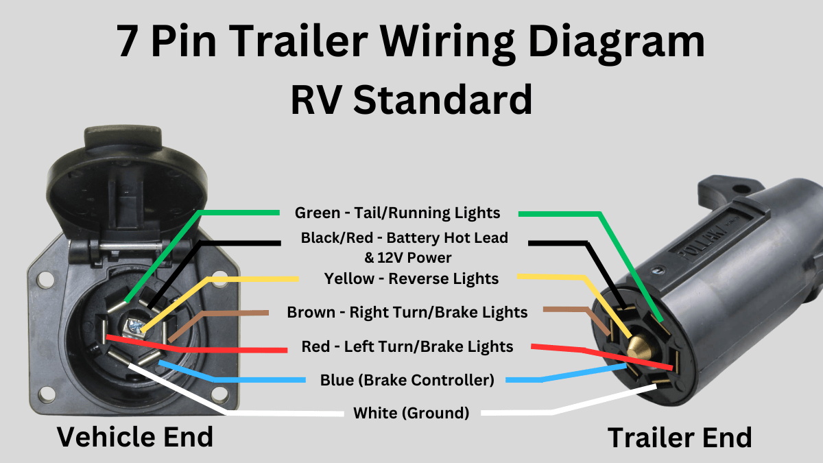
The wiring diagram will also show the pinout – the specific function assigned to each pin on the connector. This is absolutely essential for verifying proper wiring and troubleshooting issues. It is generally arranged as follows:
- Ground (White)
- Left Turn/Stop (Yellow)
- Tail/Running Lights (Brown)
- Right Turn/Stop (Green)
- Electric Brakes (Blue)
- 12V Auxiliary Power (Black)
- Reverse Lights (Red or Purple)
How It Works
When the tow vehicle is connected to the camper, the electrical signals from the vehicle are transmitted through the 7-pin connector to the corresponding circuits on the trailer. For example, when you activate the turn signal, the tow vehicle sends a signal through the appropriate pin (yellow for left, green for right) to activate the corresponding turn signal on the trailer. Similarly, when you press the brake pedal, a signal is sent to the brake lights and, if equipped, to the electric brakes. The black wire provides a 12V power source, allowing the camper battery to charge while towing or powering interior lights or other accessories.
The ground wire (white) provides a common return path for all electrical circuits, ensuring proper current flow. A good ground connection is critical for proper operation.
Real-World Use: Basic Troubleshooting Tips
Here are some common issues and troubleshooting steps:
- No Lights:
- Check the tow vehicle's fuses.
- Inspect the 7-pin connectors for corrosion or damage. Clean or replace as needed.
- Verify the ground connection on both the tow vehicle and the camper.
- Use a multimeter to test for voltage at each pin on the tow vehicle's connector when the corresponding function is activated (e.g., turn signal, brake pedal).
- Inspect the trailer's wiring harness for breaks or shorts.
- Brakes Not Working:
- Verify the electric brake controller on the tow vehicle is functioning correctly and properly adjusted.
- Check the blue wire connection and continuity between the tow vehicle and the trailer.
- Inspect the brake magnets in the trailer's wheels for wear or damage.
- Battery Not Charging:
- Check the black wire connection and continuity.
- Verify the tow vehicle's charging system is working correctly.
- Check the camper's battery for proper voltage and charge level.
- Inspect any in-line fuses or circuit breakers on the 12V auxiliary power circuit.
Use a multimeter to diagnose electrical issues. Set the multimeter to DC voltage mode to measure voltage, continuity mode to check for broken wires or bad connections, and resistance mode to check for shorts. Always disconnect the power source before working on electrical circuits.
Safety Considerations
Working with electrical systems can be dangerous. Always disconnect the battery before performing any work. Be especially careful when dealing with the 12V auxiliary power circuit, as it can deliver a significant amount of current. Short circuits can cause fires and damage to electrical components.
Electric brakes are a critical safety feature. If you suspect a problem with your electric brakes, have them inspected by a qualified technician. Do not tow a trailer with malfunctioning brakes.
When making repairs or modifications, use appropriately sized wiring and connectors. Ensure all connections are secure and properly insulated. Improper wiring can lead to overheating, short circuits, and electrical fires.
Pay special attention to the ground connection. A poor ground can cause a variety of electrical problems. Clean and tighten all ground connections regularly.
Remember that the 12V auxiliary power is often connected directly to the tow vehicle's battery, which can be a high-current circuit. Accidental shorts to ground can cause significant sparks, melting wires, and even battery explosions. Always use caution when working with this circuit.
Before making any modifications or repairs, consult the wiring diagram for your specific camper and tow vehicle. Understanding the wiring configuration is essential for ensuring safe and reliable operation.
We have the wiring diagram file ready for you to download and use as a reference during your repairs. It includes detailed pinouts, color codes, and circuit diagrams to assist in your troubleshooting efforts.