7 Pin Trailer Wiring Kit With Brakes
So, you're ready to tackle a 7-pin trailer wiring project, eh? Whether you're upgrading your existing setup, troubleshooting a faulty connection, or diving into the world of trailer towing for the first time, understanding the 7-pin trailer wiring diagram is absolutely critical. This article will break down the complexities into manageable chunks, empowering you to confidently work on your trailer's electrical system.
Why Bother Understanding 7-Pin Trailer Wiring?
The 7-pin connector is the workhorse of trailer wiring, providing connections for more than just basic lights. It handles things like running lights, brake lights, turn signals, a 12V auxiliary power supply (for charging a trailer battery or powering interior lights), and crucially, electric trailer brakes. Without a clear understanding of how this system functions, you risk damaged components, safety hazards, and potential legal issues if your trailer isn't operating correctly.
This diagram matters for several reasons:
- Repairs: Diagnosing and fixing wiring problems become significantly easier when you know where each wire is supposed to go and what it's supposed to do.
- Upgrades: Adding features like trailer brakes or auxiliary power requires a solid understanding of the existing wiring.
- Safety: Faulty trailer wiring can lead to brake failure, light outages, and even fires. A thorough understanding helps prevent these scenarios.
- Learning: Even if you plan to outsource the work, knowing the basics empowers you to communicate effectively with a mechanic and understand the job being done.
Key Specifications and Main Components
Before we dive into the diagram, let's cover the main components involved and their key specs.
- 7-Pin Connector (Vehicle Side): This is the receptacle mounted on your tow vehicle that accepts the trailer's plug. It should be weatherproof and securely mounted.
- 7-Pin Connector (Trailer Side): This is the plug on the trailer that connects to the vehicle's receptacle. It also needs to be durable and weatherproof.
- Wiring Harness: The bundle of wires connecting the vehicle's electrical system to the 7-pin connector. Use appropriately gauged wire (typically 12-14 gauge for most circuits, heavier gauge for brakes and auxiliary power).
- Electric Brake Controller: This device, mounted inside the tow vehicle, sends a variable voltage signal to the trailer brakes based on the vehicle's braking action. Crucial for trailers equipped with electric brakes.
- Brake Magnets: Located inside the trailer's brake drums, these magnets are energized by the brake controller and create friction against the drum, applying the brakes.
- Auxiliary Power Relay: This optional relay allows the vehicle to supply power to the trailer's auxiliary circuit only when the ignition is on, preventing the trailer from draining the vehicle's battery.
Decoding the Diagram: Symbols, Lines, and Colors
A typical 7-pin trailer wiring diagram uses a standardized set of symbols and colors to represent different components and circuits. Here's a breakdown:
- Lines: Solid lines represent wires, while dashed lines might indicate optional or less common connections. The thickness of the line doesn't necessarily correspond to wire gauge.
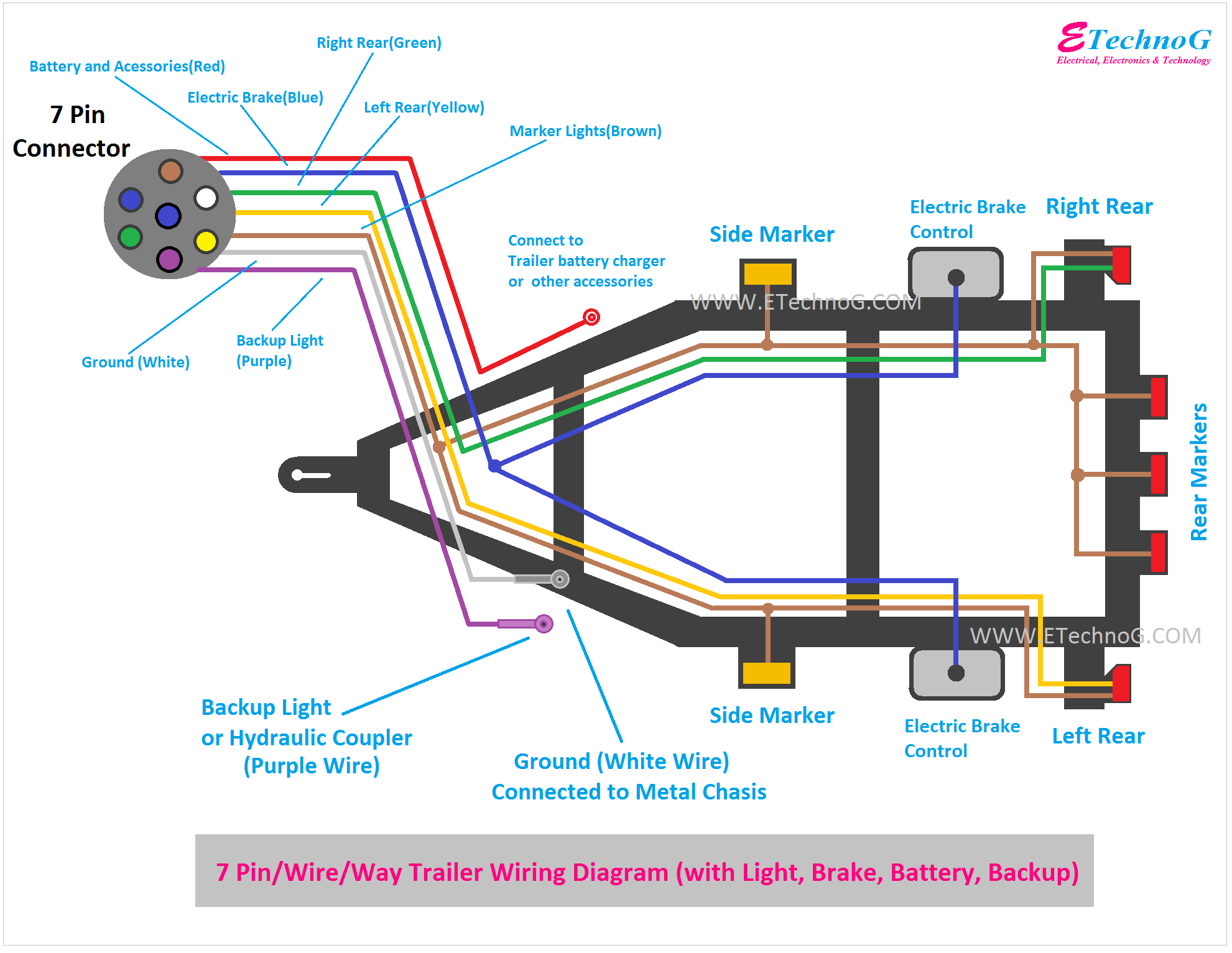
- Colors: Each wire color corresponds to a specific function. The standard colors are (but may vary, ALWAYS confirm with your vehicle's manual!):
- Yellow: Left Turn Signal & Brake Light
- Green: Right Turn Signal & Brake Light
- Brown: Tail Lights & Running Lights
- White: Ground
- Blue: Electric Brake Controller Output
- Red: Stop Lamps
- Black: 12V Auxiliary Power
- Symbols:
 : Represents a ground connection.
 : Represents a junction or splice point.
- Rectangles and other shapes: Represent components like the brake controller, battery, lights, and relays.
Important Note: While these color codes are generally standardized, always verify the pinout and function of each wire with a multimeter before making any connections. Don't rely solely on color; confirm with a multimeter!
How It Works: The 7-Pin System in Action
Here's a simplified explanation of how the 7-pin system operates:
- Lights: When you activate your vehicle's turn signals, brake lights, or running lights, the corresponding circuits in your vehicle send power through the 7-pin connector to the trailer's lights, mirroring your vehicle's signals.
- Electric Brakes: When you apply the brakes in your vehicle, the electric brake controller senses the deceleration and sends a voltage signal to the trailer's brake magnets. The higher the voltage, the stronger the braking force applied to the trailer. This allows for proportional braking, where the trailer brakes work in sync with the vehicle's brakes.
- Auxiliary Power: The 12V auxiliary power circuit provides a constant (or ignition-switched) power supply to the trailer. This can be used to charge a trailer battery, power interior lights, or run other electrical devices on the trailer.
- Ground: A solid ground connection is absolutely essential for the entire system to function correctly. A poor ground can cause erratic lighting, brake issues, and other electrical problems.
Real-World Use: Basic Troubleshooting Tips
Encountering problems with your trailer wiring? Here are a few troubleshooting tips:
- Start with the Basics: Check all connections for corrosion, loose wires, and damage. Clean and tighten connections as needed.
- Use a Multimeter: A multimeter is your best friend for diagnosing electrical problems. Use it to check for voltage, continuity, and shorts in the wiring.
- Isolate the Problem: Determine whether the issue is on the vehicle side, the trailer side, or within the connector itself.
- Check Fuses: Blown fuses are a common cause of trailer wiring problems. Inspect all relevant fuses in both the vehicle and the trailer.
- Grounding Issues: Poor grounding is often the culprit. Ensure a solid ground connection between the trailer frame and the vehicle frame. Clean any rust or corrosion.
- Test Lights Individually: If only one light is malfunctioning, test the bulb and the wiring directly connected to that light.
Example: If your trailer lights are dim or flickering, first check the ground connection. A corroded ground connection will restrict current flow, resulting in dim lights. Clean the connection with a wire brush and apply dielectric grease to prevent future corrosion.
Safety First: Handling Risky Components
Working with electrical systems always carries some risk. Here are some safety precautions to take:
- Disconnect the Battery: Always disconnect the vehicle's battery before working on any wiring to prevent accidental shorts.
- Use Proper Tools: Use insulated tools designed for electrical work.
- Wear Safety Glasses: Protect your eyes from debris and sparks.
- Work in a Well-Ventilated Area: If you're using soldering equipment or working with chemicals, ensure adequate ventilation.
- Double-Check Connections: Before reconnecting the battery, carefully double-check all your connections to ensure they are secure and properly insulated.
- The Brake Controller: The brake controller can deliver significant voltage/current. Treat it carefully, and ensure the connections are robust. Short circuits here could cause damage to both the brake controller and the vehicle's electrical system.
- Auxiliary Power Line: If your auxiliary power line is connected directly to the vehicle's battery without a fuse, a short circuit could cause a fire. ALWAYS use a properly sized fuse on this line.
Disclaimer: This article provides general guidance and should not be considered a substitute for professional advice. If you are unsure about any aspect of trailer wiring, consult a qualified mechanic or electrician.
We have a detailed 7-pin trailer wiring diagram available for download. It provides a visual representation of the wiring connections, making it easier to understand and troubleshoot your trailer's electrical system. This diagram will include color codes, pin assignments, and typical component layouts. Having this visual aid will be invaluable as you work on your project. Consider it your blueprint for success! Click the button below to access the diagram.
Remember, electrical work requires care and precision. Double-check your connections, use quality components, and never hesitate to seek professional help if you're unsure about something. Good luck, and happy towing!
This is the end of the article. Please note that the image placeholders needs to be properly defined as images. Also, consider adding more details about the functionality of each pin and its real-world implications. Additionally, the download button requires javascript function with the code for downloading the file.