7 Pin Trailer Wiring Kit With Electric Brakes
Understanding a 7-pin trailer wiring diagram, especially when dealing with electric brakes, is crucial for anyone towing regularly. Whether you're installing a new kit, troubleshooting a faulty connection, or simply expanding your automotive knowledge, knowing how each wire functions is essential for safe and reliable towing. This article will break down the intricacies of a 7-pin trailer wiring system with electric brakes, providing you with the knowledge to diagnose issues and make informed decisions.
Purpose of Understanding the 7-Pin Trailer Wiring Diagram
The 7-pin wiring harness is the backbone of connecting your tow vehicle to your trailer. It provides the electrical connections necessary for lights, brakes, and other trailer functions. Understanding the diagram allows you to:
- Diagnose Electrical Problems: Pinpointing shorts, opens, or incorrect wiring.
- Install a New Wiring Kit: Ensuring proper connections for all functions.
- Troubleshoot Lighting Issues: Identifying problems with brake lights, turn signals, or running lights.
- Maintain Your Trailer: Performing preventative maintenance to avoid future problems.
- Enhance Safety: Ensuring your trailer brakes function correctly.
Key Specs and Main Parts
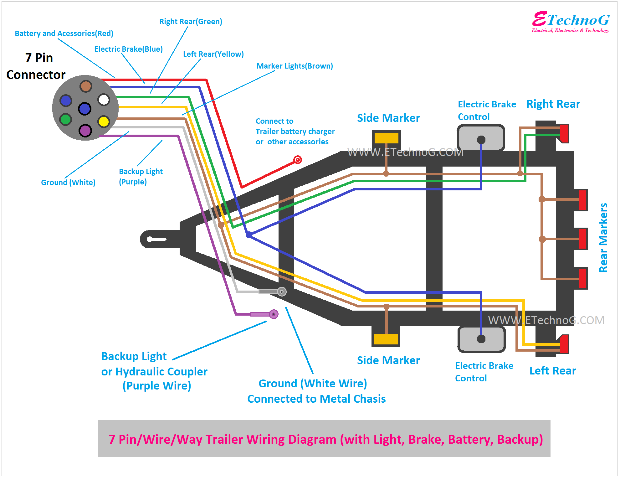
A 7-pin trailer connector uses seven distinct pins, each with a specific function. The connector itself comes in two primary forms: the vehicle-side connector (typically mounted on the hitch receiver) and the trailer-side connector. Here's a breakdown of common 7-pin configurations (although slight variations may exist, this is the most common):
- Pin 1 (Yellow): Left Turn/Brake Light
- Pin 2 (Blue): Electric Brakes
- Pin 3 (White): Ground
- Pin 4 (Green): Right Turn/Brake Light
- Pin 5 (Brown): Tail/Running Lights
- Pin 6 (Red): Auxiliary (often used for a 12V+ power supply or reverse lights)
- Pin 7 (Black): 12V+ Power Supply (Battery Charge Line)
Beyond the connector itself, several other components are essential in a 7-pin trailer wiring system with electric brakes:
- Trailer Brake Controller: Mounted in the tow vehicle, this device sends a variable voltage signal to the trailer brakes, proportional to the tow vehicle's braking force. Modern controllers often use inertial sensors to detect deceleration.
- Breakaway Switch: A critical safety device. In the event of trailer detachment, a cable connected to the tow vehicle pulls a pin on the breakaway switch, activating the trailer brakes.
- Wiring Harness: The collection of wires running between the connectors and the various lights and brakes on the trailer and tow vehicle. Using the correct gauge (thickness) of wire is crucial, especially for the electric brake circuit.
- Fuses and Circuit Breakers: Protect the wiring from overload.
Understanding the Wiring Diagram: Symbols and Conventions
Wiring diagrams use specific symbols to represent components and connections. While the exact style can vary, common symbols include:
- Straight Lines: Represent wires. Thicker lines may indicate heavier-gauge wires.
- Circles: Can represent bulbs (lights), but sometimes are just connection points.
- Rectangles: Often represent components like the brake controller or fuse boxes.
- Ground Symbol (often three horizontal lines decreasing in length): Indicates a connection to the vehicle's chassis (ground).
- Colors: Wire colors are crucial for identification. The standard color codes are outlined in the pin descriptions above, but always double-check the diagram.
The diagram will typically show how each pin on the connector is wired to its respective component (e.g., the blue wire connects to the brake controller output, which then connects to the trailer brake magnets). Understanding the "flow" of electricity through the system is essential.
How It Works: Electric Brakes in Action
The heart of the 7-pin system, particularly for larger trailers, is the electric brake circuit. Here's how it functions:
- When the driver applies the brakes in the tow vehicle, the brake controller senses this deceleration.
- The brake controller sends a voltage signal (varying from 0 to 12 volts) to the blue wire (Pin 2) of the trailer connector. The amount of voltage sent depends on the severity of the braking.
- This voltage travels through the blue wire to the trailer's electric brake magnets.
- The brake magnets, when energized, are pulled against the brake drum (or rotor), creating friction and slowing the trailer wheels. The strength of the magnetic pull is directly proportional to the voltage applied.
- The white wire (Pin 3) provides the ground connection for the brake magnets and all other trailer circuits. A good, clean ground connection is critical for proper operation.
Real-World Use: Basic Troubleshooting Tips
Here are some common problems and troubleshooting steps you can take:
- No Trailer Lights: Start by checking the fuses on both the tow vehicle and the trailer. Then, inspect the ground connection (white wire) for corrosion or looseness. Use a multimeter to check for voltage at the trailer connector pins when the corresponding lights are activated on the tow vehicle.
- One Trailer Light Not Working: Check the bulb first. If the bulb is good, trace the wiring from the bulb back to the connector, looking for breaks or loose connections.
- Electric Brakes Not Working: First, verify that the brake controller is functioning correctly in the tow vehicle. Many controllers have a display that indicates output voltage. Check the blue wire connection at both the tow vehicle and the trailer. Use a multimeter to measure the voltage at the brake magnet when the brake controller is activated. If there's voltage, inspect the brake magnets themselves for damage.
- Trailer Brakes Locking Up: This often indicates a problem with the brake controller settings (gain too high) or a short in the blue wire. Reduce the brake controller gain. Inspect the blue wire for chafing or damage that could be causing it to short to ground.
- Breakaway Switch Activation: If the breakaway switch activates unexpectedly, check the condition of the breakaway cable and the switch itself. The switch can become corroded or damaged, leading to false activation.
Safety Considerations
Working with electrical systems can be dangerous. Here are some crucial safety tips:
- Disconnect the Battery: Always disconnect the negative terminal of the tow vehicle's battery before working on the wiring.
- Use a Multimeter Safely: Understand how to use a multimeter correctly and safely. Never probe live circuits without proper training and eye protection.
- Wear Eye Protection: Protect your eyes from sparks and debris.
- Use Properly Sized Wiring: Using undersized wiring can lead to overheating and fire. Consult a wiring chart to determine the appropriate gauge for each circuit. The brake circuit is especially sensitive to this.
- Ensure a Good Ground: A poor ground connection can cause all sorts of electrical problems. Clean and tighten all ground connections.
- Trailer Brakes are *Critical*: Never tow a trailer with malfunctioning brakes. It's illegal and incredibly dangerous. Regularly inspect your trailer brakes and wiring.
Working on trailer wiring, especially electric brakes, requires attention to detail and a solid understanding of electrical principles. Always double-check your work and consult a qualified technician if you're unsure about any aspect of the process. Remember that safety is paramount.
For your convenience, we have a detailed 7-pin trailer wiring diagram file available for download. This diagram provides a visual representation of the wiring connections and can be a valuable resource for troubleshooting and repair. Please feel free to reach out if you have any questions.