7 Pin Trailer Wiring Kit With Lights
Let's dive into the world of 7-pin trailer wiring! Understanding this system is crucial for anyone looking to tow safely and legally, whether you're hauling a camper, boat, or utility trailer. This article will break down the 7-pin trailer wiring kit with lights, covering everything from its purpose and key components to troubleshooting tips. We'll approach this from the perspective of a seasoned mechanic explaining things clearly to an experienced DIYer, focusing on practical knowledge and clear explanations.
Purpose and Importance
Why bother understanding the 7-pin trailer wiring system? Several reasons stand out:
- Safe Towing: Proper wiring ensures your trailer lights function correctly, increasing visibility and preventing accidents.
- Legal Compliance: Most jurisdictions require working trailer lights for legal towing. A malfunctioning system can lead to fines and prevent you from using your trailer.
- DIY Repairs and Modifications: Understanding the wiring allows you to diagnose and fix issues yourself, saving time and money compared to professional repairs.
- Customization: Need to add extra lighting or features to your trailer? Knowing the wiring lets you modify the system safely and effectively.
- Learning & Education: Deepening your understanding of automotive electrical systems, which can be beneficial for future projects.
Think of this as a deep dive into the circulatory system of your trailer. Just like blood is essential for a body to function, electricity is essential for a trailer to be seen and safe on the road.
Key Specs and Main Parts of a 7-Pin Trailer Wiring Kit
The 7-pin connector is the backbone of this system. It's designed to provide connections for various lighting and auxiliary functions. Here's a breakdown of the key components:
- 7-Pin Connector (Vehicle Side): Typically mounted on the tow vehicle, this connector receives the electrical signals and distributes them to the trailer.
- 7-Pin Connector (Trailer Side): Located on the trailer, this connector accepts the electrical signals from the tow vehicle and routes them to the appropriate lights and accessories.
- Wiring Harness: A collection of color-coded wires that connect the vehicle's electrical system to the 7-pin connector. The length and gauge (thickness) of these wires are critical for reliable operation.
- Trailer Lights: These include:
- Tail Lights: Provide basic visibility when driving at night.
- Brake Lights: Indicate when the brakes are being applied.
- Turn Signals: Signal intended lane changes or turns.
- Side Marker Lights: Enhance visibility of the trailer's length, especially at night.
- License Plate Light: Illuminates the trailer's license plate.
- Electric Brake Controller (Optional): Required for trailers with electric brakes. The 7-pin connector includes a dedicated pin for brake signal.
- Auxiliary Power (Optional): Some trailers use the 7-pin connector to provide 12V power for interior lights, batteries, or other accessories.
Understanding the 7-Pin Wiring Diagram Symbols
Wiring diagrams use a universal set of symbols to represent electrical components and connections. Understanding these symbols is crucial for interpreting the diagram and troubleshooting issues.
- Lines: Represent wires. Different line styles can indicate wire gauge or type (e.g., solid lines for standard wires, dashed lines for shielded wires).
- Circles: Often represent connection points or splices.
- Rectangles: Can represent various components, such as relays, switches, or fuses.
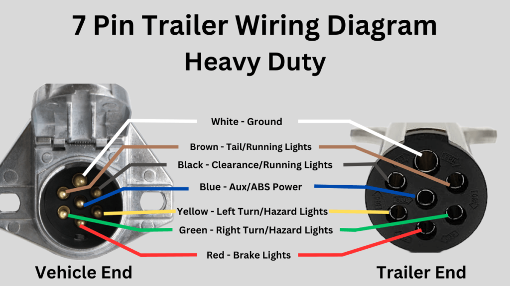
- Color Codes: Standard color codes are used to identify the function of each wire. Common colors include:
- Yellow: Left Turn/Stop
- Green: Right Turn/Stop
- Brown: Tail/Running Lights
- White: Ground
- Blue: Electric Brake Controller Output
- Red: Auxiliary Power (12V+)
- Black: Reverse Lights (Sometimes, not always in standard kits)
- Ground Symbol: Typically represented by a series of horizontal lines decreasing in length, indicating a connection to the vehicle's chassis or a dedicated ground point. Proper grounding is essential for the entire system to function correctly.
How the 7-Pin Trailer Wiring System Works
The 7-pin wiring system works by transferring electrical signals from the tow vehicle to the trailer. When you activate a specific function in the vehicle (e.g., turn signal, brakes), the corresponding electrical signal is sent through the wiring harness to the 7-pin connector. The connector then routes the signal to the appropriate lights or accessories on the trailer.
Here's a simplified breakdown of the process:
- You activate a function in the tow vehicle (e.g., turn signal).
- The vehicle's electrical system sends an electrical signal to the corresponding wire in the wiring harness.
- The signal travels through the wiring harness to the vehicle-side 7-pin connector.
- The signal passes through the connected 7-pin connectors (vehicle and trailer).
- The signal travels through the trailer's wiring to the appropriate light or accessory.
- The light or accessory activates.
- The white ground wire ensures that a return path for the current exists, allowing the electricity to flow in a complete circuit.
For trailers equipped with electric brakes, the brake controller in the tow vehicle sends a variable voltage signal through the blue wire to the trailer's electric brakes. The voltage is proportional to the braking force applied in the tow vehicle.
Real-World Use: Basic Troubleshooting Tips
Even with careful installation, problems can arise. Here are some basic troubleshooting tips for common issues:
- No Lights: Check the ground connection. A bad ground is the most common cause of lighting problems. Use a multimeter to verify continuity between the trailer's ground wire and the vehicle's chassis.
- One Light Not Working: Check the bulb first. If the bulb is good, check the wiring connections and look for any damaged or corroded wires.
- Brake Lights Not Working: Check the brake light switch on the tow vehicle. Also, check the wiring and connections to the brake controller (if applicable).
- Turn Signals Not Working: Check the turn signal bulbs on both the tow vehicle and the trailer. Also, check the flasher relay.
- Intermittent Problems: These can be the trickiest to diagnose. Check all wiring connections for looseness or corrosion. Vibration can cause intermittent connections to fail. Consider using dielectric grease on all connections to prevent corrosion.
- Using a Multimeter: A multimeter is your best friend when troubleshooting electrical issues. Use it to check for voltage, continuity, and resistance. Always disconnect the power source before working on electrical components.
- Test Light: Simple tool, which can quickly check if a wire is receiving power, useful for tracing the source of an electrical issue.
Safety Considerations
Working with electrical systems can be dangerous. Here are some important safety precautions:
- Disconnect the Battery: Always disconnect the negative terminal of the tow vehicle's battery before working on the wiring system. This will prevent accidental shorts and electrical shocks.
- Use Proper Tools: Use insulated tools designed for electrical work.
- Wear Safety Glasses: Protect your eyes from sparks and debris.
- Work in a Well-Ventilated Area: Some electrical components can emit fumes when heated.
- Be Aware of Airbags: Disconnecting electrical connectors near airbags can trigger them. Consult your vehicle's repair manual for specific instructions.
- Fuses: Always replace blown fuses with fuses of the same amperage rating. Using a higher amperage fuse can overload the circuit and cause a fire.
The electric brake controller circuit is a high-current circuit. Ensure that the wiring is properly sized to handle the current requirements of the trailer's brakes. Undersized wiring can overheat and cause a fire.
Always double-check your work before connecting the battery. Verify that all connections are secure and that there are no exposed wires.
We have a detailed 7-pin trailer wiring diagram available for download. This diagram provides a visual representation of the wiring connections and can be a valuable resource for troubleshooting and repairs. Please contact us for the download link.