
7 Pin Trailer Wiring To 4 Pin Adapter
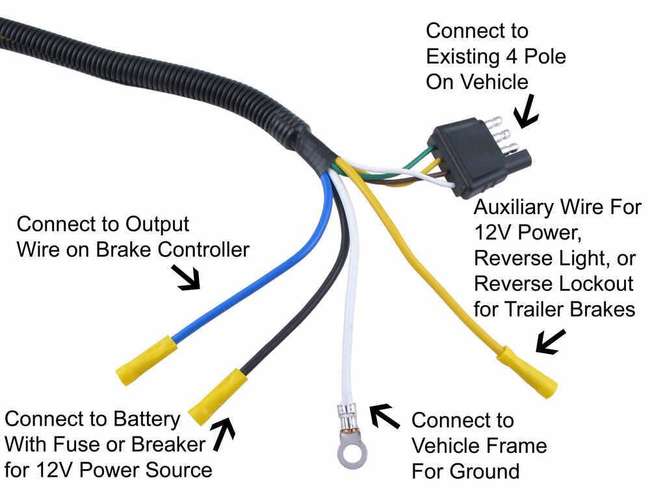
If you're a seasoned DIYer or getting more involved in your vehicle's electrical systems, understanding trailer wiring is a crucial skill. This article focuses on the common task of adapting a 7-pin trailer connector to a 4-pin connector. We'll break down the wiring, explain the functions, and provide you with practical troubleshooting tips.
Purpose of Understanding 7-Pin to 4-Pin Adapters
Why bother learning about this? The primary reason is compatibility. Vehicles often come equipped with a 7-pin trailer connector (commonly known as an RV blade connector), while many smaller trailers, especially those for light-duty hauling, use a 4-pin flat connector. An adapter bridges this gap, allowing you to tow a 4-pin trailer with a vehicle that has a 7-pin connector. Understanding the wiring is essential for:
- Safe Towing: Ensuring lights function correctly.
- Troubleshooting: Diagnosing and fixing lighting issues.
- DIY Modifications: Adding or upgrading trailer electrical systems.
- Preventing Damage: Avoiding electrical shorts and blown fuses.
Key Specs and Main Parts
Let's define the main components and their functions:
- 7-Pin Connector (RV Blade): This connector provides circuits for running lights, turn signals, brake lights, a 12V auxiliary power circuit, reverse lights, and electric brakes (if equipped).
- 4-Pin Connector (Flat): This connector offers circuits for running lights, left turn/brake light, right turn/brake light, and a ground.
- Adapter: The adapter itself is the physical bridge, typically a molded plastic or rubber housing with corresponding pins and sockets to connect the two types.
- Wiring: The wires themselves are the pathways for electrical current. They are color-coded to denote their function, which we'll discuss shortly. Typically 16 gauge wire is more than sufficient for the purpose.
Here's a table summarizing the standard functions of each pin:
| Pin | 7-Pin Function | 4-Pin Function |
|---|---|---|
| 1 | Ground | Ground (White) |
| 2 | Tail/Running Lights | Tail/Running Lights (Brown) |
| 3 | Left Turn/Brake Light | Left Turn/Brake Light (Yellow) |
| 4 | Right Turn/Brake Light | Right Turn/Brake Light (Green) |
| 5 | Electric Brakes | N/A |
| 6 | Auxiliary 12V Power | N/A |
| 7 | Reverse Lights | N/A |
Symbols: Understanding Wiring Diagrams
Wiring diagrams are crucial for understanding how the adapter works. Here's a breakdown of common symbols:
- Solid Lines: Represent wires. Thicker lines sometimes indicate higher amperage circuits.
- Dotted Lines: Often used to represent wires that are optional or not always present.
- Circles with Numbers: Represent connector pins, with the number indicating the pin assignment.
- Color Codes: Wires are color-coded for easy identification. Common colors include white (ground), brown (running lights), yellow (left turn/brake), green (right turn/brake), blue (electric brakes), red (auxiliary power), and black (sometimes auxiliary power or battery charge).
- Ground Symbol (looks like an upside down tree): Indicates a connection to the vehicle's chassis, providing a return path for the electrical current.
- Battery Symbol: Represents the vehicle's battery.
- Light Bulb Symbol: Represents a light bulb.
- Fuse Symbol: Represents a fuse, a safety device that protects the circuit from overcurrent.
How It Works: Wiring the Adaptation
The adapter's function is to intelligently map the essential 4-pin functions from the 7-pin connector. This means:
- Ground (White): The ground pin on the 7-pin is directly connected to the ground pin on the 4-pin. A proper ground is absolutely crucial for all lights to function.
- Running Lights (Brown): The running light pin on the 7-pin is connected to the running light pin on the 4-pin. This powers the taillights on the trailer when the vehicle's headlights are on.
- Left Turn/Brake (Yellow): The left turn/brake pin on the 7-pin is connected to the left turn/brake pin on the 4-pin. This powers the left turn signal and brake light on the trailer. The 4-pin system combines these functions into a single wire.
- Right Turn/Brake (Green): The right turn/brake pin on the 7-pin is connected to the right turn/brake pin on the 4-pin. This powers the right turn signal and brake light on the trailer. Again, the 4-pin system combines these functions.
The 7-pin's electric brake, auxiliary power, and reverse light circuits are not used in a standard 7-pin to 4-pin adapter. These functionalities are lost when using the adapter because the 4-pin connector does not have corresponding pins. If your trailer requires electric brakes or other auxiliary power, you'll need to rewire the trailer or use a different towing setup.
Real-World Use: Troubleshooting
Here are some common troubleshooting tips when using a 7-pin to 4-pin adapter:
- No Lights: Check the vehicle's fuses related to trailer lights. A blown fuse is the most common cause. Also, ensure the ground connection is clean and secure. A poor ground can cause all sorts of lighting problems.
- Dim Lights: This often indicates a poor ground connection or corrosion in the connectors. Clean the connector pins with electrical contact cleaner.
- One Light Not Working: Check the light bulb itself. Also, inspect the wiring on the trailer for any breaks or shorts.
- Brake Lights Don't Work: Test your vehicle's brake lights first to rule out a problem with the vehicle itself. Then, check the wiring on the trailer and the adapter.
- Lights Work Intermittently: This often indicates a loose connection. Carefully inspect all connections and ensure they are tight and secure.
To test, use a multimeter set to DC voltage. Check for voltage at the appropriate pins on the 7-pin connector on the vehicle when the lights are activated. If you don't get voltage, the problem is with the vehicle wiring, not the adapter or trailer.
Safety Considerations
Working with electrical systems involves risk. Here are some important safety precautions:
- Disconnect the Battery: Always disconnect the vehicle's negative battery terminal before working on the electrical system. This prevents accidental shorts and potential damage.
- Use Proper Tools: Use insulated tools designed for electrical work.
- Avoid Water: Never work on electrical systems in wet conditions.
- Fuses are Important: Never replace a fuse with a higher amperage fuse. This can overload the circuit and cause a fire.
- Electric Brakes: Note that the 4-pin adapter will NOT provide electric brake functionality. If your trailer has electric brakes, do not use this adaptor unless the braking system is completely removed or bypassed. Failure to heed this warning could result in a serious accident.
Specifically, the auxiliary power (12V) circuit in the 7-pin connector can carry significant current. Shorting this wire to ground can cause a major electrical fault and potentially damage the vehicle's electrical system. Be extremely careful when working with this circuit.
Understanding the wiring diagram for a 7-pin to 4-pin adapter empowers you to troubleshoot lighting issues, perform DIY repairs, and ensure safe towing. It's a valuable skill for any DIY mechanic or car enthusiast.
To further assist you, we have a detailed wiring diagram available for download. This diagram visually illustrates the pin assignments and wire colors, making it even easier to understand how the adapter works. You can use it as a reference during troubleshooting or when making modifications to your trailer wiring.