
73-87 C10 Steering Column Wiring Diagram
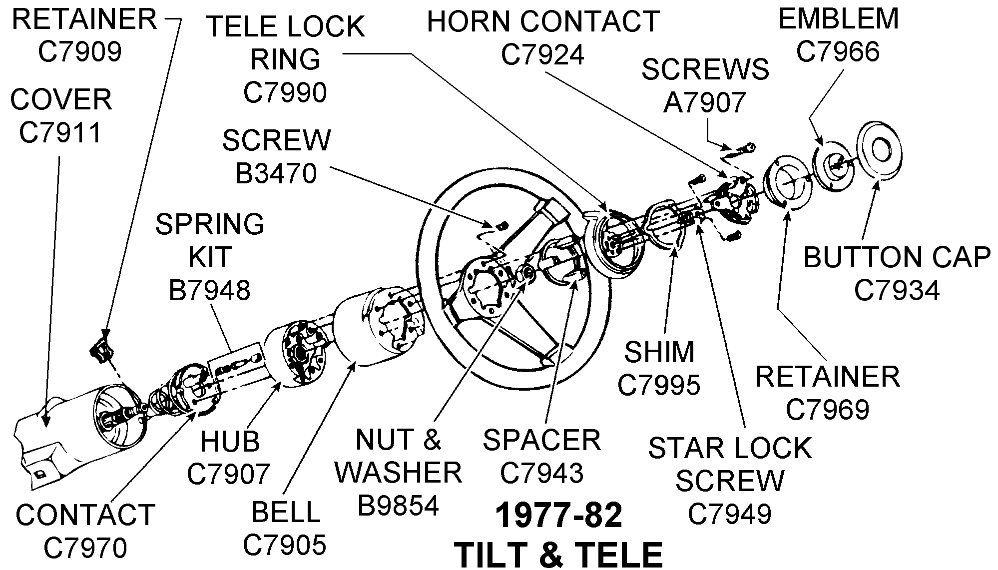
The 1973-1987 Chevrolet C10 pickup truck is an iconic vehicle, beloved for its ruggedness and simplicity. However, even the most dependable machine requires maintenance, and electrical issues, particularly within the steering column, can arise. A reliable steering column wiring diagram is an indispensable tool for any DIY mechanic or car enthusiast working on these trucks. Whether you're diagnosing a faulty turn signal, replacing a worn-out ignition switch, or attempting a custom modification, understanding the wiring is crucial to avoid costly mistakes and potential safety hazards. This article provides a comprehensive overview of the 73-87 C10 steering column wiring diagram, empowering you to tackle electrical repairs and modifications with confidence.
Purpose of the Steering Column Wiring Diagram
Why is this diagram so important? Several reasons:
- Troubleshooting Electrical Problems: The primary function is diagnosing issues within the steering column. A malfunctioning turn signal, horn, ignition switch, or hazard lights often points to a wiring problem within this area. The diagram provides a roadmap to trace circuits, identify broken wires, and pinpoint shorts or open circuits.
- Repairs and Replacements: When replacing components like the turn signal switch, ignition switch, or dimmer switch, the diagram guides you in connecting the new parts correctly. Mismatched wiring can lead to component failure or even electrical fires.
- Custom Modifications: Many C10 owners customize their trucks. Whether it's adding aftermarket accessories, installing a different steering wheel, or upgrading the gauge cluster, understanding the steering column wiring is essential for integrating these modifications safely and effectively.
- Learning Vehicle Electrical Systems: Even if you don't have an immediate problem, studying the diagram is an excellent way to learn how automotive electrical systems work in general. Understanding the flow of electricity, the function of each component, and the relationship between different circuits will greatly expand your automotive knowledge.
Key Specs and Main Parts
The 1973-1987 C10 steering column evolved slightly over the years, but the fundamental wiring remained relatively consistent. Key components you'll encounter on the diagram include:
- Ignition Switch: Controls the starting and running of the engine. It has several positions: OFF, ACC (Accessory), RUN, and START. Each position activates different circuits.
- Turn Signal Switch: Controls the left and right turn signals, as well as the hazard lights. It's a complex switch with multiple contacts and wires.
- Dimmer Switch: Located on the steering column, this switch controls the high and low beams of the headlights.
- Horn Contacts: Activated by the horn button on the steering wheel, these contacts complete the circuit to activate the horn relay.
- Hazard Flasher Switch: Activates all four turn signals simultaneously as a warning.
- Wiring Harness: The collection of wires that connect all the components together. It's crucial to identify each wire by its color code and gauge (thickness).
- Connectors: These are used to join sections of the wiring harness together, and they are common failure points. Look for corrosion or loose connections.
Typical wire gauges found in the steering column range from 18 AWG to 12 AWG, with thicker wires used for higher current circuits like the ignition and headlight circuits. Voltage is typically 12V DC.
Symbols – Decoding the Diagram
Understanding the symbols used in the wiring diagram is essential for interpreting it correctly. Here's a breakdown of common symbols:
- Lines: Represent wires. Solid lines indicate a direct connection, while dashed lines may indicate a shielded wire or a wire that passes through a connector.
- Colors: Each wire is assigned a color code (e.g., RED, BLU, GRN). These colors are crucial for identifying the correct wires. A legend on the diagram will specify the full color name (e.g., RED = Red, BLU = Blue). Sometimes, a wire will have a primary color and a stripe (e.g., WHT/BLK = White with a Black stripe).
- Circles: Often represent terminals or connection points.
- Rectangles: Can represent switches, relays, or other components. The diagram will usually label the component within the rectangle.
- Ground Symbol: Usually a series of descending horizontal lines, indicating a connection to the vehicle's chassis ground. A good ground connection is critical for proper circuit function.
- Fuses: Represented by a zig-zag line within a rectangle or a simple rectangle with a number indicating the fuse amperage rating.
Pay close attention to the line weights on the diagram. Heavier lines typically represent wires carrying higher current loads.
How It Works: Following the Circuit
Let's take the turn signal circuit as an example. When you activate the turn signal switch to signal a left turn, you are essentially closing a circuit that allows current to flow from the battery (through a fuse, for protection) to the turn signal flasher unit (which creates the blinking effect). From the flasher, the current flows through the turn signal switch and then to the appropriate left-side turn signal bulbs (front and rear). The circuit is completed when the current returns to ground, usually through the vehicle's chassis. The wiring diagram shows you the path of this current flow, the components involved, and the wire colors to identify each part of the circuit.
Similarly, the ignition switch controls power to various circuits depending on its position. In the "START" position, it energizes the starter solenoid, engaging the starter motor to crank the engine. In the "RUN" position, it provides power to the ignition system and other essential circuits.
Real-World Use: Basic Troubleshooting Tips
Here are some practical troubleshooting tips using the steering column wiring diagram:
- No Turn Signals: Check the turn signal flasher unit first. Use a multimeter to verify that power is reaching the flasher and that the flasher is working. If the flasher is good, use the wiring diagram to trace the circuit to the turn signal switch and then to the individual turn signal bulbs. Look for broken wires, corroded connectors, or a faulty switch.
- Horn Not Working: Verify that the horn relay is functioning. Check the fuse for the horn circuit. If both are good, trace the wiring from the horn button on the steering wheel to the horn relay. A common problem is a broken wire within the steering column due to wear and tear from turning the wheel.
- Ignition Problems: If the engine won't start, use the wiring diagram to trace the ignition circuit. Check the ignition switch for proper operation. Use a multimeter to verify that voltage is present at the correct terminals in each switch position. Also, check the starter solenoid and the wiring connecting it to the ignition switch.
- Dim Headlights: Check the dimmer switch on the steering column. These switches can become corroded and fail to properly switch between high and low beams. A bad ground for the headlight circuit can also cause dim headlights.
Always use a multimeter to test for voltage and continuity. A multimeter is an essential tool for diagnosing electrical problems. A test light can also be helpful for quick checks, but it doesn't provide as much information as a multimeter.
Safety First!
Working with automotive electrical systems can be dangerous. Here are some safety precautions:
- Disconnect the Battery: Always disconnect the negative battery cable before working on any electrical components. This prevents accidental shorts and potential electrical fires.
- Be Aware of the Airbag: If your C10 is equipped with an airbag, be extremely careful when working on the steering column. Accidental deployment of the airbag can cause serious injury. Follow the manufacturer's instructions for disarming the airbag system before starting any work.
- Use Proper Tools: Use insulated tools designed for automotive electrical work. This reduces the risk of electric shock.
- Work in a Well-Ventilated Area: Some electrical components can emit fumes when overheated or damaged. Work in a well-ventilated area to avoid inhaling these fumes.
- Don't Modify Wiring Arbitrarily: Always refer to the wiring diagram before making any modifications to the wiring. Incorrect wiring can damage components or create safety hazards.
The ignition switch and airbag system (if equipped) are especially sensitive components. Handle them with care and consult the service manual for proper procedures.
With a solid understanding of the 73-87 C10 steering column wiring diagram, and a commitment to safe practices, you'll be well-equipped to diagnose and repair electrical issues in your classic truck. Remember that patience and meticulous attention to detail are key to success.
We have the 73-87 C10 Steering Column Wiring Diagram file. You can download it here.