73 87 Chevy Truck Air Conditioning Wiring Diagram
The 1973-1987 Chevrolet (and GMC counterpart) truck, often referred to as the "Squarebody," is a beloved platform for restoration, modification, and general DIY automotive enthusiasts. A functioning air conditioning system is often a key component to restoring or upgrading these trucks. Understanding the A/C wiring diagram is paramount for diagnosing issues, performing repairs, and even integrating aftermarket components. This article provides a detailed breakdown of the 1973-1987 Chevy Truck A/C wiring diagram, tailored for the experienced DIYer.
Purpose of Understanding the Wiring Diagram
Why bother learning about this seemingly complex web of wires? There are several compelling reasons:
- Diagnostics: A failing A/C system can be frustrating. The wiring diagram allows you to trace circuits, identify voltage drops, and pinpoint faulty components like relays, switches, or sensors.
- Repairs: Replacing a damaged wire, connector, or even a component requires understanding how it integrates into the overall system. The diagram provides that crucial context.
- Modifications: Adding aftermarket A/C systems, electric fans, or other related components becomes significantly easier with a solid understanding of the original wiring layout. You can integrate new parts seamlessly without creating electrical nightmares.
- Learning: Expanding your automotive knowledge and skills is always valuable. Mastering the A/C wiring diagram enhances your troubleshooting abilities for any vehicle.
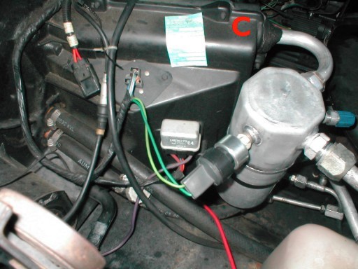
Key Specs and Main Parts
Before diving into the diagram itself, it's essential to understand the core components of the A/C system and some critical specifications. While there may be slight variations based on trim level and year, the fundamental principles remain consistent.
Main Components:
- Compressor: The heart of the system, driven by the engine, compresses the refrigerant.
- Condenser: Located in front of the radiator, dissipates heat from the refrigerant.
- Evaporator: Located inside the cab, absorbs heat from the cabin air, cooling it.
- Expansion Valve (or Orifice Tube): Controls the flow of refrigerant into the evaporator.
- Receiver Drier (or Accumulator): Filters and removes moisture from the refrigerant.
- A/C Clutch: Engages and disengages the compressor pulley from the crankshaft.
- Blower Motor: Circulates air through the evaporator and into the cabin.
- Pressure Switches: Protect the system from over-pressure and low-pressure conditions. These can include a high-pressure cutoff switch and a low-pressure cycling switch.
- Mode Selector Switch: Controls which vents the air is directed to.
- Temperature Control Switch: Regulates the temperature of the air coming out of the vents.
- Wiring Harness: The network of wires that connects all the components together.
- Fuses and Relays: Protect the circuits from overloads and control high-current components.
Key Specs:
- Voltage: The system operates on a 12-volt DC electrical system, common for automotive applications.
- Fuse Ratings: Specific fuse ratings for the A/C circuit vary but are typically in the 10-20 amp range. Consult the vehicle's owner's manual or a specific wiring diagram for accurate ratings.
- Wire Gauge: The thickness of the wires (measured in AWG - American Wire Gauge) varies depending on the current load. Higher current components, like the blower motor, will use thicker gauge wires.
Understanding Wiring Diagram Symbols
Wiring diagrams use standardized symbols to represent components, wires, and connections. Familiarizing yourself with these symbols is crucial for interpreting the diagram correctly.
- Lines: Solid lines represent wires. Dashed lines may indicate optional connections or components specific to certain models or years.
- Colors: Wires are color-coded to aid in identification. Common colors include red (power), black (ground), blue, green, yellow, and white. The diagram legend will define the color codes.
- Component Symbols: Each component has a specific symbol. A few key examples:
- Resistor: A zig-zag line.
- Capacitor: Two parallel lines.
- Diode: A triangle pointing to a line.
- Ground: A series of descending lines, often resembling an upside-down Christmas tree.
- Switch: A line bridging a gap. The type of switch (e.g., SPST, SPDT, DPST) is indicated by the number of poles and throws.
- Relay: A coil symbol representing the electromagnet, and a switch symbol representing the contacts.
- Fuse: A small "S" shape inside a rectangle.
- Wire Splices/Connections: A dot indicates a connection between wires. If lines cross without a dot, they are not connected.
- Text Labels: Labels are used extensively to identify components, wire numbers, and circuit functions.
Pay close attention to the legend accompanying the wiring diagram. The legend explains the specific symbols and color codes used in that particular diagram.
How the A/C Wiring Works (Simplified)
The A/C system's electrical circuit can be broken down into a simplified flow:
- Power Source: The circuit receives power from the vehicle's battery, typically through a fuse in the fuse box.
- Ignition Switch: Often, the A/C system is enabled only when the ignition switch is in the "ON" position.
- Mode Selector Switch and Temperature Control Switch: These switches control various functions, like enabling the blower motor and adjusting the air temperature.
- Pressure Switches: The high-pressure and low-pressure switches act as safety devices. If the refrigerant pressure is too high or too low, these switches open the circuit, preventing the compressor from engaging and potentially damaging the system.
- A/C Clutch Relay: When all conditions are met (ignition on, proper pressure, A/C switch activated), the A/C clutch relay is energized. This relay sends power to the A/C clutch, engaging the compressor.
- Compressor Clutch: With the clutch engaged, the compressor begins to circulate refrigerant, starting the cooling process.
- Blower Motor: The blower motor, independently controlled by the mode selector switch, circulates air through the evaporator and into the cabin.
- Ground: All circuits must have a proper ground connection to complete the electrical path.
Real-World Use: Basic Troubleshooting Tips
Here are a few basic troubleshooting tips, using the wiring diagram as your guide:
- No A/C at all: Check the A/C fuse first. If the fuse is blown, replace it with one of the correct amperage rating. If it blows again immediately, there's a short circuit somewhere in the system. Use the diagram to trace the circuit and identify potential problem areas.
- A/C clutch not engaging: Use a multimeter to check for voltage at the A/C clutch connector when the A/C is turned on. If there's no voltage, check the A/C clutch relay and the pressure switches. A faulty relay or an open pressure switch could be the cause.
- Blower motor not working: Check the blower motor fuse. If the fuse is good, check the blower motor resistor pack. This resistor pack controls the blower motor speed. If the resistor pack is faulty, the blower motor may not work at all or may only work on certain speeds.
- Continuity Testing: A multimeter set to continuity mode can be used to check for broken wires or faulty connections. Disconnect the battery before performing continuity testing.
Safety Precautions
Working on automotive electrical systems can be dangerous. Observe the following safety precautions:
- Disconnect the Battery: Always disconnect the negative battery terminal before working on any electrical components. This prevents accidental shorts and potential damage.
- High-Pressure Refrigerant: Be extremely cautious when working with the A/C system itself. Refrigerant is under high pressure and can cause severe frostbite if released improperly. Only qualified technicians should handle refrigerant.
- Correct Fuses: Always replace fuses with the correct amperage rating. Using a fuse with a higher rating can overload the circuit and cause a fire.
- Proper Grounding: Ensure all components are properly grounded. Poor grounding can cause erratic behavior and electrical damage.
- Wiring Insulation: Protect wires from abrasion and damage. Use proper wiring looms and connectors to ensure safe and reliable connections.
Remember, this guide provides a general overview. Always consult a specific wiring diagram for your year and model of Chevy/GMC truck. With careful study and a methodical approach, understanding and troubleshooting your Squarebody's A/C wiring becomes a manageable and rewarding task.
You can download the full detailed wiring diagram here to use while working on your vehicle.