73-87 Chevy Truck Ignition Wiring Harness Diagram
The 1973-1987 "Square Body" Chevy/GMC trucks are iconic, representing a golden age of American work vehicles. Whether you're restoring one, performing maintenance, or even undertaking a modern engine swap, understanding the ignition wiring harness is absolutely crucial. This article delves into the specifics of that harness, providing the knowledge you need to diagnose problems, make repairs, and modify your truck with confidence. We even have a downloadable diagram available for you to use.
Purpose of Understanding the Ignition Wiring Harness
Why bother dissecting a seemingly complex web of wires? Here’s why:
- Troubleshooting: Ignition problems are common in older vehicles. A faulty wire, a corroded connector, or a bad sensor can leave you stranded. Knowing the wiring diagram allows you to systematically trace circuits and pinpoint the source of the issue.
- Restoration: During a restoration, the wiring harness might be damaged, brittle, or incomplete. Understanding the diagram enables you to repair or replace sections accurately, ensuring correct functionality.
- Modification: Swapping in a newer engine, installing aftermarket ignition systems, or adding accessories requires a solid understanding of the existing wiring. The diagram provides a roadmap for integrating new components without causing electrical mayhem.
- Learning: Even if you're not actively working on your truck, studying the ignition wiring diagram enhances your understanding of automotive electrical systems. This foundational knowledge is invaluable for any DIY mechanic.
Key Specs and Main Parts
The ignition wiring harness on these trucks isn't overly complicated compared to modern vehicles, but it's important to understand its core components:
- Ignition Switch: The heart of the system. It controls the flow of power to various circuits based on the key position (Off, Acc, Run, Start).
- Battery: The power source, typically a 12-volt system. It supplies the necessary voltage to operate the ignition system and other electrical components.
- Starter Solenoid: A heavy-duty relay that engages the starter motor to crank the engine.
- Distributor: Contains the ignition module (often called the HEI module in later models) and the pickup coil. The distributor is responsible for timing the ignition spark.
- Ignition Coil: Steps up the 12-volt battery voltage to the thousands of volts needed to create a spark at the spark plugs.
- Spark Plugs: The final destination for the high-voltage spark, igniting the air/fuel mixture in the cylinders.
- Ballast Resistor (or Resistance Wire): Found in earlier models (generally pre-HEI), it reduces the voltage to the ignition coil during the "Run" position to protect the coil. HEI systems do *not* use a ballast resistor.
- Wiring Harness: The collection of wires connecting all these components.
Symbols: Decoding the Wiring Diagram
A wiring diagram uses a standardized set of symbols to represent electrical components and connections. Here’s a breakdown of the most common symbols you'll encounter:
- Lines: Solid lines represent wires. Dashed lines might indicate shielded wires or wires that are only present on certain models or with specific options. Wire thickness is often indicated by a gauge number (e.g., 12 AWG, 16 AWG).
- Colors: Each wire is coded with a specific color (e.g., Red, Black, Orange, Purple). Color codes are essential for tracing wires and ensuring proper connections. The diagram will include a color key.
- Circles: Can represent various components, but often denote connectors or junction points.
- Rectangles: Typically represent switches, relays, or control modules.
- Ground Symbol: Usually a series of horizontal lines descending in length, indicating a connection to the vehicle's chassis (ground).
- Fuse Symbol: A squiggly line enclosed in a rectangle, representing a fuse. The fuse rating (in Amperes) will usually be indicated.
- Relay Symbol: A coil of wire representing the relay's electromagnet and a switch representing the relay's contacts.
Understanding Wire Colors: Pay close attention to the wire colors. They are critical for identifying the correct wires within the harness. Common colors include:
- Red: Typically indicates a power wire directly from the battery (often fused).
- Black: Generally represents ground.
- Orange: Often used for circuits that are hot in the "Run" or "Accessory" positions.
- Purple: Commonly used for the starter solenoid wire.
- Yellow: May be used for ignition-related circuits.
- Brown: Often associated with lighting circuits.
How It Works: The Ignition Sequence
The ignition system is responsible for creating the spark that ignites the air/fuel mixture in the engine's cylinders. Here's a simplified overview of the process:
- Key Position: When you turn the key to the "Start" position, the ignition switch sends power to the starter solenoid.
- Starter Engagement: The starter solenoid closes, sending power to the starter motor, which cranks the engine.
- Power to Ignition: Simultaneously, the ignition switch sends power to the ignition coil and the distributor (or ignition module in HEI systems) when the key is in either the "Run" or "Start" position. In pre-HEI systems this power would pass through a Ballast Resistor.
- Distributor Operation: The distributor, driven by the engine's camshaft, rotates and triggers the ignition module. In HEI systems, the module uses a pickup coil to determine when to trigger.
- Coil Charging: The ignition module controls the charging and discharging of the ignition coil. When the module triggers, it interrupts the coil's primary circuit.
- Spark Generation: This interruption causes the magnetic field in the coil to collapse rapidly, inducing a high-voltage current in the coil's secondary winding.
- Spark Distribution: The high-voltage current is sent to the distributor cap, which directs the spark to the appropriate spark plug based on the engine's firing order.
- Combustion: The spark ignites the air/fuel mixture in the cylinder, initiating the combustion process.
Real-World Use: Basic Troubleshooting Tips
Here are some common ignition-related problems and how to use the wiring diagram to diagnose them:
- No Start:
- Check the battery voltage. A low battery is a common cause of no-start conditions.
- Verify that the starter motor is receiving power when the key is in the "Start" position. Use the wiring diagram to trace the purple wire from the ignition switch to the starter solenoid.
- Inspect the ignition switch itself. A faulty switch can prevent power from reaching the ignition system.
- If you have a pre-HEI system, test the ballast resistor. A failed ballast resistor will prevent the engine from starting or running properly.
- Engine Cranks But Doesn't Start:
- Check for spark at the spark plugs. If there's no spark, the problem could be with the ignition coil, distributor, or ignition module.
- Use the wiring diagram to verify that the ignition coil is receiving power.
- Inspect the distributor cap and rotor for cracks or damage.
- Intermittent Stalling or Misfiring:
- Loose or corroded wiring connections can cause intermittent problems. Carefully inspect all connections in the ignition circuit, using the wiring diagram as a guide.
- A failing ignition module can cause intermittent stalling or misfiring.
Safety Considerations
Working with electrical systems can be dangerous. Here are some important safety precautions:
- Disconnect the Battery: Always disconnect the negative battery cable before working on any electrical components. This prevents accidental shorts and potential electrocution.
- High-Voltage Components: The ignition coil and spark plug wires carry extremely high voltage. Never touch these components while the engine is running or when the ignition is switched on.
- Fuses: Never replace a blown fuse with one of a higher amperage rating. This can overload the circuit and cause a fire.
- Proper Tools: Use insulated tools designed for electrical work.
- Grounding: Ensure that the vehicle is properly grounded before testing any electrical components.
Remember, high voltage is extremely dangerous. Always exercise caution and consult a qualified mechanic if you are unsure about any procedure.
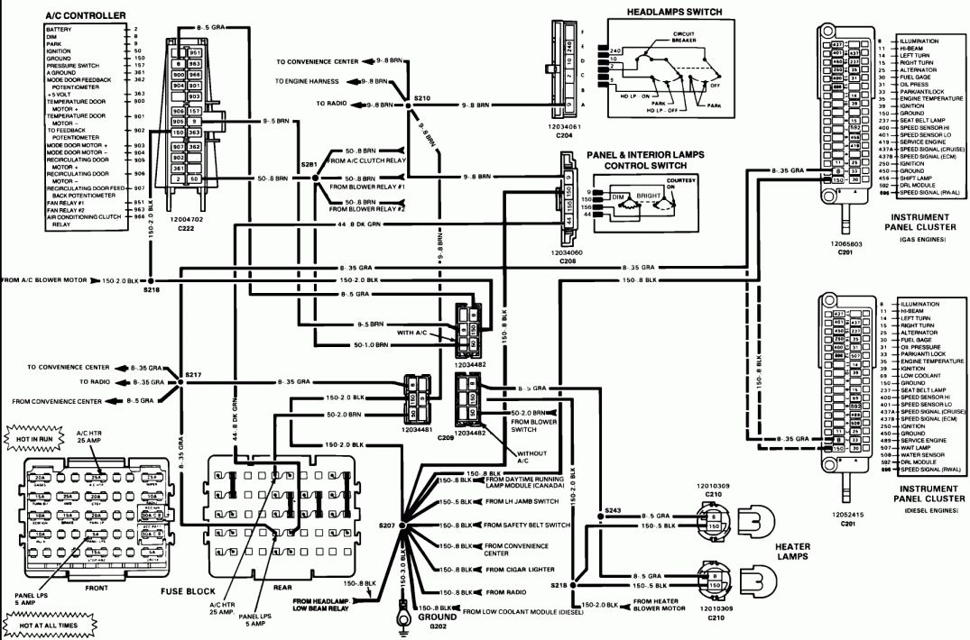
Download the Ignition Wiring Diagram
To assist you in your troubleshooting, repair, or modification projects, we have a detailed ignition wiring diagram available for download. This diagram covers the 1973-1987 Chevy/GMC truck models and provides a comprehensive overview of the ignition wiring system. We can provide it to you; just let us know you're ready.
By combining this diagram with the information provided in this article, you'll be well-equipped to tackle any ignition-related challenges on your Square Body Chevy or GMC truck. Happy wrenching!