
7.3 Powerstroke Battery Cable Diagram
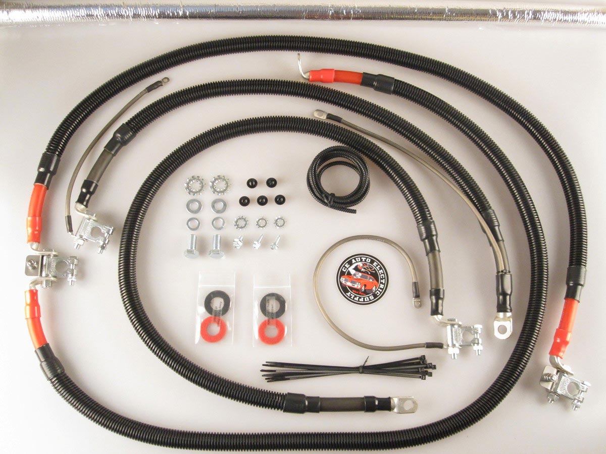
The battery cables in your 7.3L Powerstroke diesel are much more than just wires; they're the crucial arteries of your truck's electrical system. Understanding their layout, function, and potential pitfalls is essential for anyone who wants to diagnose electrical issues, perform maintenance, or even upgrade their rig. This article will delve into the 7.3 Powerstroke battery cable diagram, providing you with the knowledge to tackle electrical tasks with confidence. We'll cover the key components, the symbols used in the diagram, how the system operates, and offer some real-world troubleshooting tips.
Purpose of Understanding the Battery Cable Diagram
Why bother learning about the battery cable layout? The answer is simple: it's indispensable for:
- Troubleshooting Electrical Problems: A malfunctioning starter, alternator, or even seemingly unrelated issues can often be traced back to corroded, loose, or damaged battery cables. The diagram provides a roadmap to systematically check each connection and cable run.
- Performing Repairs and Replacements: Whether you're replacing a cable, a battery terminal, or even the entire battery setup, the diagram ensures you reconnect everything correctly, preventing potentially disastrous short circuits.
- Understanding the Charging System: The battery cables are a vital part of the charging circuit. Understanding their path allows you to diagnose charging issues and ensure proper voltage delivery.
- Upgrades and Modifications: Planning to add auxiliary lights, a winch, or a high-output alternator? The diagram will help you determine how to properly integrate these additions into your existing electrical system.
- Preventative Maintenance: Regularly inspecting your battery cables, terminals, and connections, guided by the diagram, can prevent costly and inconvenient breakdowns.
Key Specs and Main Parts
The 7.3 Powerstroke electrical system is a 12-volt DC system. Here are the key components associated with the battery cable diagram:
- Batteries: Most 7.3 Powerstroke trucks utilize two 12-volt batteries connected in parallel. This configuration maintains 12 volts but doubles the available amperage (cold cranking amps - CCA), which is crucial for starting a diesel engine in cold weather.
- Battery Terminals: These are the connection points on the batteries, typically a post or a side terminal. They are prone to corrosion and require regular cleaning.
- Positive (+) Battery Cables: These are typically red and carry the positive voltage from the batteries to various components. Crucially, one positive cable connects to the starter solenoid.
- Negative (-) Battery Cables (Ground Cables): These are typically black and provide the return path (ground) for the electrical circuit. They connect to the vehicle's chassis and engine block, providing a solid ground connection. A poor ground can cause a multitude of electrical problems.
- Starter Solenoid (Relay): A heavy-duty switch that allows the relatively low current from the ignition switch to control the high current flow to the starter motor. It's usually located on the inner fender or firewall.
- Starter Motor: The electric motor that cranks the engine to start it. It requires a large amount of current, supplied directly from the battery through the starter solenoid.
- Alternator: The component responsible for recharging the batteries and providing power to the electrical system while the engine is running. The alternator connects to the batteries via heavy gauge wiring.
- Fusible Links: These are short sections of thinner gauge wire designed to act as fuses in specific circuits. They protect vital components from overcurrent situations.
Symbols and Conventions Used in the Diagram
Understanding the symbols used in the battery cable diagram is crucial for interpreting its information. While specific diagrams might vary slightly, common conventions include:
- Solid Lines: Represent wires or cables. The thickness of the line often corresponds to the wire gauge (thicker lines indicate larger gauge wires).
- Dotted Lines: Might represent wiring that is optional, or specific to certain trim levels or years.
- Color Coding: Wire colors are usually indicated next to the lines. Common colors include:
- Red: Positive (+) voltage
- Black: Ground (-)
- Other Colors (e.g., Yellow, Blue, Green): Indicate specific circuits, like those for the starter signal, alternator exciter wire, etc. The diagram will define what each color represents.
- Battery Symbol: Shows the battery, with a "+" symbol indicating the positive terminal and a "-" symbol indicating the negative terminal.
- Ground Symbol: Represents the connection to the vehicle's chassis, providing a ground path. It often looks like a series of stacked triangles.
- Component Symbols: Various symbols represent the different components, such as the starter solenoid, alternator, and starter motor. These symbols are usually standardized but may vary slightly. Refer to the legend on the diagram for clarification.
How It Works: The Battery Cable Circuit
The 7.3 Powerstroke battery cable system is a relatively straightforward DC circuit. Here's a simplified explanation:
- Battery Connection: The batteries are connected in parallel. This means the positive terminals of both batteries are connected together, and the negative terminals are connected together. This provides 12 volts with increased amperage.
- Positive Voltage Distribution: A heavy-gauge positive cable runs from the positive battery terminal(s) to the starter solenoid. Another positive cable typically supplies power to the glow plug relay and other circuits via a fuse box or fusible link.
- Starting the Engine: When the ignition switch is turned to the "start" position, a low-current signal is sent to the starter solenoid. The solenoid closes, allowing high current from the battery to flow directly to the starter motor.
- Ground Path: The starter motor and other electrical components are grounded to the engine block or chassis via heavy-gauge negative cables. This completes the circuit, allowing current to flow.
- Charging the Batteries: Once the engine is running, the alternator charges the batteries. The alternator is connected to the batteries via heavy-gauge positive and negative cables. The alternator regulates the charging voltage to prevent overcharging the batteries.
Real-World Use: Basic Troubleshooting Tips
Here are some common problems you can diagnose using the battery cable diagram:
- Engine Cranks Slowly or Not At All:
- Check Battery Voltage: Use a multimeter to measure the voltage at the battery terminals. It should be around 12.6 volts with the engine off.
- Inspect Battery Terminals: Look for corrosion. Clean the terminals with a wire brush and baking soda solution. Apply dielectric grease to prevent future corrosion.
- Check Battery Cables: Inspect for loose connections, frayed wires, or damaged insulation. Tighten connections and replace damaged cables.
- Test Starter Solenoid: Use a multimeter to check for voltage at the starter motor when the ignition switch is in the "start" position. If there's no voltage, the solenoid may be faulty.
- Verify Ground Connections: Ensure all ground cables are securely attached to the engine block and chassis. Clean any corroded ground connections.
- Battery Light On: This indicates a problem with the charging system.
- Check Alternator Output: Use a multimeter to measure the voltage at the alternator output terminal with the engine running. It should be around 13.5-14.5 volts.
- Inspect Alternator Wiring: Check the alternator wiring harness for loose connections, damaged wires, or corroded terminals.
- Check Belt Tension: Ensure the alternator belt is properly tensioned. A loose belt can cause the alternator to slip and not charge properly.
- Electrical Components Malfunctioning: Dim lights, erratic gauge readings, or other electrical malfunctions can often be traced back to poor ground connections.
- Check Ground Connections: Inspect all ground cables and connections. Clean and tighten as needed.
Safety Considerations
Working with electrical systems can be dangerous. Here are some crucial safety precautions:
- Disconnect the Batteries: Always disconnect both battery terminals (negative first) before working on the electrical system to prevent accidental short circuits.
- Wear Safety Glasses: Protect your eyes from battery acid and debris.
- Use Insulated Tools: Use tools with insulated handles to prevent electric shock.
- Work in a Well-Ventilated Area: Batteries can produce hydrogen gas, which is explosive.
- Avoid Working on a Hot Engine: Allow the engine to cool down before working on the electrical system.
- Be Careful Around the Starter Solenoid: The starter solenoid carries a large amount of current. Avoid touching the terminals with metal objects while the batteries are connected. This component can deliver a serious shock.
- Don't Smoke or Use Open Flames: Near the batteries or fuel system.
By understanding the 7.3 Powerstroke battery cable diagram, you can confidently diagnose and repair electrical issues, ensuring your truck stays on the road. Remember to prioritize safety and consult a qualified mechanic if you're unsure about any procedure.
To help you with your troubleshooting, we have the comprehensive 7.3 Powerstroke battery cable diagram available for download. This resource will provide you with a detailed visual guide to assist in your diagnostics and repairs.