8 Pin Throttle Position Sensor Wiring Diagram
Alright, let's dive into the world of the 8-Pin Throttle Position Sensor (TPS) wiring diagram. Whether you're troubleshooting a wonky idle, planning a performance upgrade, or simply expanding your automotive know-how, understanding this diagram is crucial. This isn't just about tracing wires; it's about understanding how your engine management system "sees" your throttle input and reacts accordingly. We'll break down the diagram, explain the components, and give you some real-world tips for diagnosis and repair. We have a downloadable copy of the wiring diagram available for you to reference as you go, so you can follow along and keep it for future use.
Why Bother With the 8-Pin TPS Wiring Diagram?
The TPS is a critical component in your car's engine management system. The engine control unit (ECU), often called the engine control module (ECM), uses the signal from the TPS to determine throttle position, which is used to control various engine parameters like fuel injection, ignition timing, and idle speed. A faulty TPS, or problems within its wiring, can lead to a range of issues, including:
- Poor fuel economy
- Rough idling or stalling
- Hesitation during acceleration
- Check engine light (CEL) activation
- Difficulty starting
Therefore, understanding the TPS wiring diagram allows you to:
- Diagnose problems: Pinpoint the source of a TPS-related issue, whether it's a faulty sensor, broken wire, or poor connection.
- Perform repairs: Replace the TPS, repair damaged wiring, or clean corroded connectors with confidence.
- Understand engine operation: Gain a deeper understanding of how the engine management system works.
- Modify and upgrade: Install aftermarket components, like performance throttle bodies, safely and correctly.
- Validate replacements: Confirm that your new TPS is wired correctly for your vehicle.
Key Specs and Main Parts of the 8-Pin TPS
Let's break down the essential components associated with an 8-Pin TPS wiring diagram:
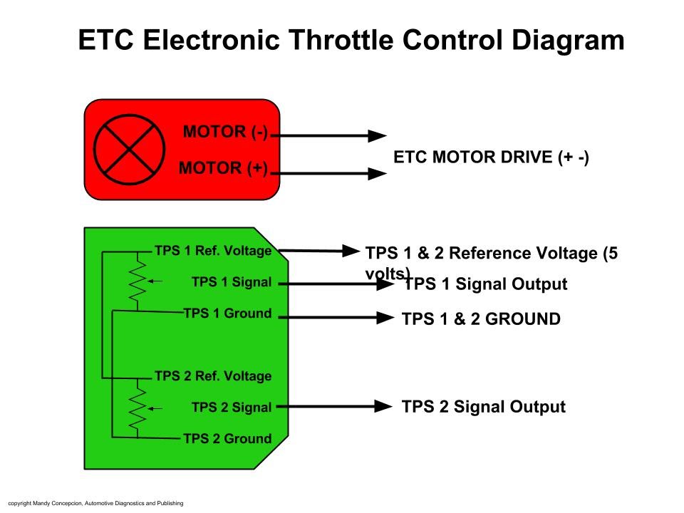
- The TPS Sensor: The heart of the system. This sensor is typically a rotary potentiometer. A potentiometer is a variable resistor whose resistance changes as the throttle plate rotates. Modern TPS sensors can also incorporate redundancy, effectively having two potentiometers within the same unit, increasing reliability and providing a cross-check for the ECU.
- Wiring Harness: This connects the TPS to the ECU and other components. It consists of multiple wires, each with a specific function, neatly bundled together.
- Connectors: These provide a secure and reliable connection between the TPS, wiring harness, and ECU. Corrosion and loose connections are common culprits in TPS-related problems.
- ECU (Engine Control Unit): The "brain" of the operation. The ECU receives the TPS signal, processes it, and controls engine functions based on the throttle position.
While referred to as an 8-pin TPS, not all pins may be actively used depending on the vehicle and sensor design. Common connections include:
- VREF (Voltage Reference): Typically a stable 5V supply from the ECU. This provides a consistent voltage for the TPS to use.
- Signal (SIG): The output signal from the TPS, varying with throttle position. This is the crucial data the ECU needs. Usually, voltage will increase as throttle angle increases.
- Ground (GND): Provides a common ground reference for the TPS.
- IDLE Switch (IDL): Some TPS units incorporate an idle switch, sending a signal when the throttle is fully closed. This can be a dedicated connection or integrated with the main signal.
- Secondary Signal (SIG2): Used in redundant TPS systems for signal verification.
- Other pins: May be used for temperature compensation or diagnostic purposes, depending on the specific application.
Decoding the Symbols: A Guide to Understanding the Diagram
Wiring diagrams use standardized symbols to represent electrical components and connections. Understanding these symbols is essential for interpreting the diagram correctly.
- Lines: Represent wires. Different line thicknesses may indicate wire gauge (thicker lines = larger gauge wires). Dashed lines often indicate shielded wires.
- Colors: Wires are color-coded for easy identification. Refer to the diagram's legend for the specific color code used in your vehicle. Common colors include Red (power), Black (ground), and various colors for signal wires.
- Circles/Dots: Indicate wire connections. A solid dot means the wires are connected, while a junction without a dot means the wires are crossing but not connected.
- Rectangles: Often represent connectors. The rectangle will typically have numbered or lettered pins that correspond to the wiring harness and sensor pins.
- Ground Symbol: A series of horizontal lines decreasing in length, indicating a connection to the vehicle's chassis ground.
- Voltage Source Symbol: Represented by a line with a positive (+) symbol, indicating the source of voltage (e.g., battery, ECU).
Note: Wiring diagrams often include additional information, such as wire gauge, connector type, and component location. Refer to your vehicle's specific service manual for the most accurate and complete information.
How It Works: From Throttle to ECU
Here's a simplified explanation of how the TPS system functions:
- When you press the accelerator pedal, the throttle plate rotates, opening the throttle bore.
- The TPS, mechanically linked to the throttle plate, rotates along with it.
- As the TPS rotates, the resistance of the potentiometer changes.
- This change in resistance alters the voltage signal sent to the ECU. For example, as the throttle opens, the signal voltage might increase from 0.5V at idle to 4.5V at wide-open throttle (WOT).
- The ECU reads this voltage signal and interprets it as the throttle position.
- Based on the throttle position, the ECU adjusts fuel injection, ignition timing, and other engine parameters to optimize performance and efficiency.
The ECU uses a lookup table or algorithms to translate the TPS voltage into a specific throttle position percentage. This percentage is then used to calculate the required fuel and ignition timing. Any deviations from expected values can trigger diagnostic trouble codes (DTCs) and illuminate the check engine light.
Real-World Use: Basic Troubleshooting Tips
If you suspect a problem with your TPS, here are some basic troubleshooting steps:
- Check for Diagnostic Trouble Codes (DTCs): Use an OBD-II scanner to read any stored DTCs. Common TPS-related codes include P0120, P0121, P0122, P0123.
- Visually Inspect the Wiring and Connectors: Look for damaged wires, loose connections, and corrosion. Clean corroded connectors with electrical contact cleaner.
- Test the TPS Voltage: Using a multimeter, measure the voltage at the TPS signal wire with the ignition on, engine off. The voltage should change smoothly as you slowly open the throttle. Jumps, dead spots, or incorrect voltage ranges indicate a faulty sensor.
- Check the TPS Ground: Ensure the TPS is properly grounded by measuring the resistance between the TPS ground pin and the vehicle's chassis ground. The resistance should be very low (close to zero ohms).
- Verify the VREF Voltage: Use a multimeter to confirm you have a stable 5V reference signal at the VREF pin.
- Perform a TPS Reset or Calibration: Some vehicles require a TPS reset or calibration after replacing the sensor. Refer to your vehicle's service manual for the specific procedure.
Example: Let's say you get a P0121 code (TPS Range/Performance Problem). You'd first visually inspect the wiring and connectors. Then, you'd use a multimeter to measure the TPS signal voltage. If the voltage is erratic or doesn't change smoothly as you open the throttle, the TPS is likely faulty. You would then replace the TPS and possibly perform a TPS reset procedure using a scan tool.
Safety First: Highlight Risky Components
When working on automotive electrical systems, safety is paramount. Here are some key safety precautions:
- Disconnect the Battery: Always disconnect the negative battery cable before working on any electrical components. This prevents accidental shorts and electrical shock.
- Avoid Working on a Hot Engine: Allow the engine to cool down completely before working on the TPS or its wiring.
- Use Proper Tools: Use insulated tools designed for automotive electrical work.
- Be Careful Around Fuel Lines: Fuel lines are often located near the TPS. Be careful not to damage them.
- Consult the Service Manual: Always refer to your vehicle's service manual for specific procedures and safety precautions.
- ECU Caution: The ECU is a sensitive electronic component. Avoid static electricity discharge when handling the ECU or its connectors. It is best to always ground yourself.
Remember, some components, like the fuel pump relay and fuel injectors, carry significant voltage even with the ignition off. Disconnecting the battery is crucial to avoid potential hazards.
By understanding the 8-Pin TPS wiring diagram and following these guidelines, you can effectively diagnose and repair TPS-related problems, improve your understanding of engine management systems, and ensure the safe and reliable operation of your vehicle. Don't hesitate to consult your vehicle's service manual for more specific information and procedures. Now you can download the 8-Pin TPS wiring diagram we mentioned earlier to reference.