88-98 Chevy Headlight Wiring Diagram
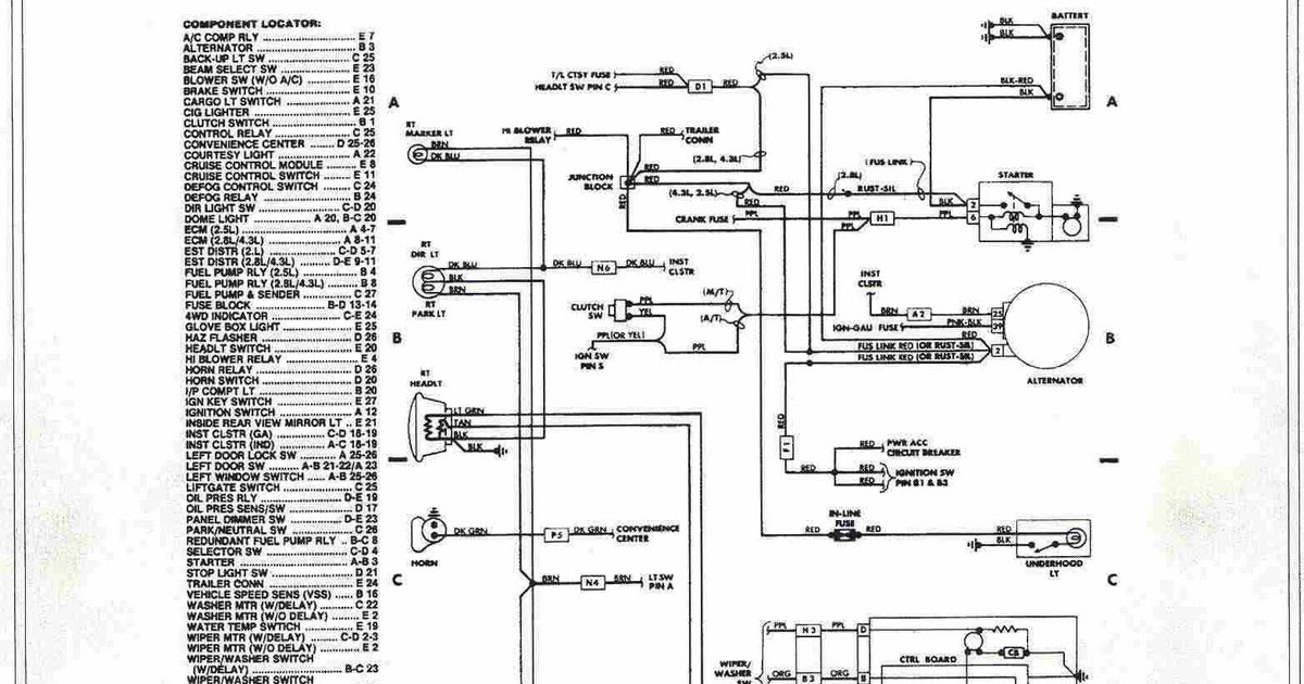
Understanding the headlight wiring diagram for your 1988-1998 Chevrolet or GMC truck (often referred to as the OBS – Old Body Style – Chevy) is crucial for various tasks, from basic repairs and bulb replacements to advanced modifications like installing aftermarket headlights or troubleshooting electrical issues. This guide provides a detailed walkthrough of the diagram, enabling you to confidently work on your vehicle's lighting system. We have a printable version of the wiring diagram available for download; you'll find the link at the end of this article.
Purpose of Understanding the Headlight Wiring Diagram
Why bother learning this? Several compelling reasons exist:
- Repairing Faulty Headlights: Quickly identify broken wires, bad grounds, or malfunctioning components, saving you time and money on professional repairs.
- Installing Aftermarket Headlights: Safely and correctly connect aftermarket headlights, ensuring proper functionality and preventing damage to your electrical system. This includes projectors, halos, and LED upgrades.
- Troubleshooting Electrical Problems: Trace circuits to diagnose shorts, open circuits, or voltage drops that could be affecting your headlights or other electrical components.
- Adding Auxiliary Lights: Wire in fog lights, driving lights, or off-road lights, integrating them seamlessly into your existing system.
- Learning Automotive Electrical Systems: Gaining a fundamental understanding of how automotive electrical systems work, starting with a relatively simple system like headlights.
Key Specs and Main Parts of the 88-98 Chevy Headlight Circuit
The 88-98 Chevy headlight circuit is a relatively straightforward 12V DC system. The key components include:
- Battery: The power source for the entire electrical system, providing 12 volts of direct current (DC).
- Headlight Switch: A multi-position switch that controls the headlights (high and low beams), parking lights, and sometimes fog lights (if equipped).
- Dimmer Switch: Typically located on the steering column, this switch controls the selection between high and low beams.
- Headlight Bulbs: The actual light-emitting elements, typically halogen bulbs (H4656, H4651, or similar depending on the year and model) but often upgraded to LEDs.
- Fuses/Circuit Breakers: Protective devices that interrupt the circuit if an overcurrent condition occurs, preventing damage to the wiring and components. Specific fuse locations will vary depending on your vehicle's year and trim.
- Relays: Electrically operated switches that allow a low-current circuit (from the headlight switch) to control a high-current circuit (to the headlights). These are crucial for preventing excessive current draw through the headlight switch, which can cause it to overheat and fail. Older models might use direct switching (without relays), but adding relays is a common upgrade.
- Wiring Harness: A bundle of wires that connects all the components together. The wiring harness is color-coded for easy identification.
- Ground Connections: Critical for completing the circuit and ensuring proper operation. Poor ground connections are a common cause of headlight problems. These grounds are typically connected to the vehicle's chassis.
Understanding the Symbols in the Wiring Diagram
Wiring diagrams use standardized symbols to represent electrical components and connections. Here's a breakdown of the common symbols you'll encounter:
- Lines: Solid lines represent wires. Thicker lines may indicate wires carrying higher current. Dashed lines may represent ground connections or control circuits.
- Color Codes: Each wire is assigned a color code (e.g., BLK for black, RED for red, BLU for blue, WHT for white, GRN for green, YEL for yellow, ORG for orange, BRN for brown). These color codes are crucial for identifying the correct wires when troubleshooting. Always double-check the wire color before making any connections.
- Circles: Often represent connections or splices in the wiring harness.
- Rectangles: Typically represent components like switches, relays, or fuses. Internal symbols within the rectangle will indicate the component's function.
- Ground Symbol: A series of downward-pointing lines, indicating a connection to the vehicle's chassis ground. A good ground is essential for proper circuit operation.
- Bulb Symbol: A circle with an "X" inside, representing a light bulb.
- Fuse Symbol: A squiggly line within a rectangle, representing a fuse.
- Relay Symbol: Shows the relay coil (a looped wire) and the switch contacts (a line connecting two points).
How the Headlight Circuit Works
The basic operation is as follows:
- Power from the battery flows through a fuse or circuit breaker, providing overcurrent protection.
- The power reaches the headlight switch.
- When the headlight switch is turned on, it sends power to either the parking lights or the headlights, depending on the switch position.
- If the headlights are selected, power flows to the dimmer switch on the steering column.
- The dimmer switch determines whether the high beams or low beams are activated.
- From the dimmer switch, power flows to the headlight bulbs.
- The headlight bulbs illuminate, and the circuit is completed through a ground connection back to the battery.
Relays (if present) insert themselves into this sequence. Instead of the headlight switch directly powering the headlights, it powers a relay. The relay then closes, allowing a high-current circuit directly from the battery (protected by a fuse) to power the headlights. This reduces the load on the headlight switch and provides brighter headlights. It is also possible to have separate relays for the high beam and low beam.
Real-World Use: Basic Troubleshooting Tips
Here are some common headlight problems and how the wiring diagram can help you diagnose them:
- Headlights Don't Work At All: Check the fuses first. If the fuses are good, use a multimeter to check for voltage at the headlight switch. If there's no voltage, trace the wiring back to the battery, looking for breaks or loose connections. If you have voltage at the switch, check the switch itself for continuity.
- One Headlight Doesn't Work: Check the bulb first. If the bulb is good, check for voltage at the bulb connector. If there's no voltage, trace the wiring back from the bulb, checking for breaks or loose connections. Pay close attention to ground connections.
- Headlights Are Dim: This is often caused by a poor ground connection or voltage drop in the wiring. Check the ground connections for corrosion and clean them thoroughly. Use a multimeter to check for voltage drop between the battery and the headlights. Anything more than a few tenths of a volt indicates a problem.
- Headlights Flicker: This can be caused by a loose connection or a faulty headlight switch. Check all connections for tightness and corrosion.
- High Beams Don't Work: Check the dimmer switch. Use a multimeter to check for continuity when the switch is in the high beam position.
When troubleshooting, always use a multimeter to check for voltage and continuity. A test light can also be useful, but a multimeter provides more accurate information. Always disconnect the negative battery cable before working on any electrical components.
Safety Considerations
Working with automotive electrical systems can be dangerous. Here are some safety precautions to keep in mind:
- Disconnect the Negative Battery Cable: This is the most important safety precaution. Disconnecting the negative battery cable prevents accidental shorts and electrical shocks.
- Work in a Well-Lit Area: Good lighting will help you see what you're doing and avoid mistakes.
- Use Proper Tools: Use insulated tools designed for automotive electrical work.
- Avoid Working in Wet Conditions: Water can conduct electricity and increase the risk of electrical shock.
- Be Careful Around the Battery: Batteries contain sulfuric acid, which is corrosive. Wear eye protection and gloves when working near the battery.
- Be Aware of Airbags: Some wiring harnesses may run near airbag sensors. Consult your vehicle's repair manual before disconnecting any wiring harnesses near airbags. Accidental airbag deployment can cause serious injury.
The headlight circuit itself generally doesn't pose a high-voltage threat, but the battery is always a potential source of danger. Shorting the positive terminal of the battery to ground can generate tremendous heat and potentially cause a fire or explosion.
By carefully studying the wiring diagram and following these safety precautions, you can confidently troubleshoot and repair the headlight system on your 88-98 Chevy or GMC truck. Remember to take your time, double-check your work, and consult a professional if you're unsure about anything.
Ready to get started? We've prepared a printable version of the 88-98 Chevy Headlight Wiring Diagram for your convenience. Click here to download the diagram now.