93 Ford Ranger Stereo Wiring Diagram
Whether you're battling a dead radio, upgrading your sound system, or just trying to understand the inner workings of your trusty 1993 Ford Ranger, a solid understanding of its stereo wiring is crucial. This article dives deep into the 93 Ford Ranger stereo wiring diagram, providing you with the knowledge and tools to confidently tackle common audio-related issues. We'll cover everything from identifying key components to basic troubleshooting, ensuring you stay safe and informed every step of the way.
Purpose of Understanding the Stereo Wiring Diagram
Why bother with a wiring diagram? Several compelling reasons exist:
- Repairing Malfunctions: A diagram is indispensable when diagnosing and fixing issues like blown fuses, speaker problems, or a completely unresponsive head unit. Pinpointing the problem without blindly guessing saves time and potential damage.
- Upgrading Your Stereo System: Planning to install a new head unit, amplifier, or speakers? The diagram shows you exactly where each wire connects, ensuring a clean and functional install. You'll avoid cutting the wrong wires and potentially damaging your electrical system.
- Learning Automotive Electrical Systems: Understanding the stereo wiring is a great starting point for grasping more complex automotive electrical concepts. It's a relatively simple circuit, making it ideal for beginners.
- Restoring a Classic: If you're restoring a '93 Ranger, the original stereo system might be damaged or missing. The diagram helps you recreate the original wiring and install a period-correct or aftermarket system with confidence.
Key Specs and Main Parts of the 1993 Ford Ranger Stereo System
The 1993 Ford Ranger stereo system is relatively straightforward. Here's a breakdown of the key components and specifications:
- Head Unit (Radio): This is the central control unit for the entire system. It typically houses the AM/FM tuner, cassette player (if equipped), and controls for volume, tone, and balance.
- Speakers: The Ranger usually came with two speakers in the doors. Some models may have had optional rear speakers. The speakers are responsible for converting the electrical audio signal into sound waves.
- Wiring Harness: This bundle of wires connects the head unit to the speakers, power source, and ground. The harness typically includes dedicated wires for power, ground, speakers (left front, right front, possibly left rear, right rear), illumination, and possibly a power antenna.
- Antenna: Receives radio signals. The standard Ranger came with a fixed mast antenna.
- Fuses: These are safety devices that protect the stereo system from overcurrent. A blown fuse indicates a problem in the circuit. The fuse location and amperage rating will be listed in your owner's manual or on the fuse box cover.
Understanding Wiring Diagram Symbols: A Visual Key
Wiring diagrams use a standardized set of symbols to represent electrical components and connections. Understanding these symbols is crucial for interpreting the diagram correctly. Here's a breakdown of common symbols you'll encounter in the 1993 Ford Ranger stereo wiring diagram:
- Solid Lines: Represent wires. The thickness of the line does not typically indicate wire gauge, although some diagrams may use thicker lines for higher current circuits.
- Dashed Lines: Can represent shielded wires or grounds. It's always best to refer to the diagram's legend for clarification.
- Circles with Numbers/Letters: These indicate connector pin numbers. They tell you exactly which pin on a connector a specific wire connects to.
- Ground Symbol (often three horizontal lines getting progressively shorter): Indicates a connection to the vehicle's chassis ground. This is the return path for the electrical current.
- Speaker Symbol (a circle with a wavy line inside): Represents a speaker.
- Fuse Symbol (a wavy line between two straight lines): Represents a fuse. The diagram will usually indicate the fuse's amperage rating.
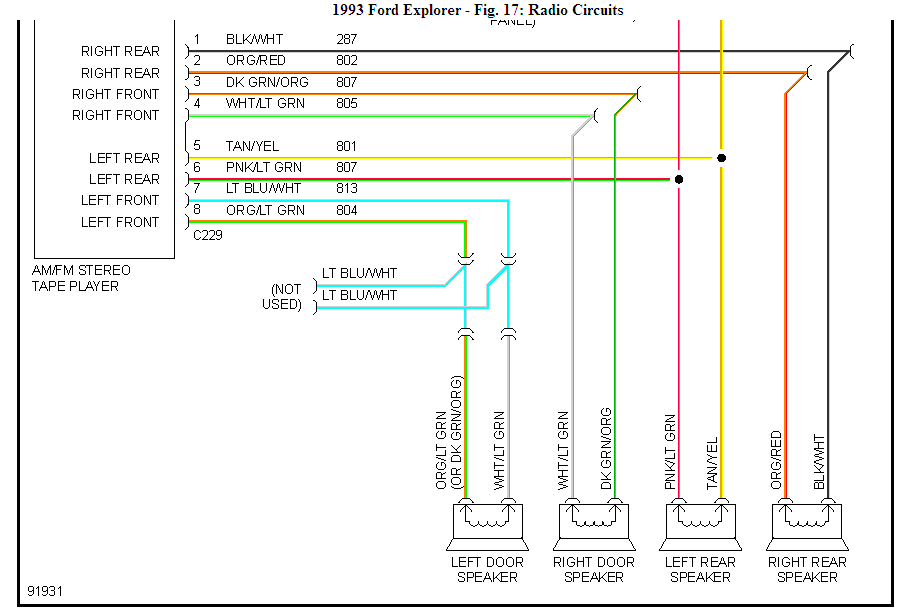
- Colors: Wire colors are critical for identification. The diagram will list the color code for each wire (e.g., Red, Black, Yellow/Black stripe). Use this to match the wires in your vehicle's harness.
Important: Always consult the legend or key on the wiring diagram itself for a comprehensive list of symbols and their meanings. Different diagrams may use slightly different conventions.
How It Works: Tracing the Stereo Circuit
The basic operation of the stereo system involves the following:
- Power Source: The head unit receives power from the vehicle's battery through the ignition switch. This allows the stereo to turn on and off with the ignition. A constant power source is also used to maintain memory settings, like radio presets.
- Ground: The head unit and other components are connected to the vehicle's chassis ground. This provides a return path for the electrical current.
- Signal Generation: The head unit receives radio signals from the antenna. It then processes these signals and amplifies them. For cassette players, the head unit reads the magnetic tape and converts it into an audio signal.
- Amplification: The amplified audio signal is then sent to the speakers.
- Sound Production: The speakers convert the electrical audio signal into sound waves, which you hear.
The wiring diagram allows you to trace this circuit step-by-step. You can see exactly where the power comes from, how the signals are routed, and where the speakers are connected.
Real-World Use: Basic Troubleshooting Tips
Here are some common stereo problems and how the wiring diagram can help you troubleshoot them:
- No Power to the Head Unit: Check the fuses first using the wiring diagram to locate the correct fuse. If the fuse is blown, replace it. If it blows again immediately, there's a short circuit somewhere in the wiring. Use the diagram to trace the power wire and look for damaged insulation or exposed wires. Also, verify the ground connection is secure and clean.
- Speakers Not Working: Use the diagram to identify the speaker wires. Check the connections at the speaker and at the head unit. Use a multimeter to test the speaker wires for continuity (a complete circuit). If there's no continuity, the wire is broken or disconnected. You can also test the speaker itself by disconnecting it and measuring its resistance (impedance). A reading of zero or infinity indicates a faulty speaker.
- Poor Sound Quality: Check the speaker wires for damage or corrosion. Ensure the speaker cones are not damaged. Verify the head unit's tone and balance settings are correct.
- Radio Reception Issues: Check the antenna connection at the head unit and at the antenna base. Make sure the antenna mast is intact.
Using a Multimeter: A multimeter is an indispensable tool for troubleshooting electrical problems. It can measure voltage, current, and resistance. Consult your multimeter's manual for instructions on how to use it safely and effectively.
Safety First: Handling Electrical Components
Working with automotive electrical systems can be dangerous. Always take the following precautions:
- Disconnect the Battery: Before working on any electrical component, disconnect the negative terminal of the battery. This prevents accidental short circuits and electrical shocks.
- Use Insulated Tools: Use tools with insulated handles to prevent electrical shocks.
- Work in a Well-Ventilated Area: When soldering wires, work in a well-ventilated area to avoid inhaling fumes.
- Identify Risky Components: The capacitors in the head unit can store a charge even after the power is disconnected. Avoid touching these components unless you know how to safely discharge them. Consult a qualified technician if you're unsure.
- Never Work Alone: It's always a good idea to have someone nearby in case of an emergency.
- Proper Grounding: Ensure all ground connections are secure and free of corrosion. A poor ground can cause a variety of electrical problems.
Disclaimer: Automotive electrical systems can be complex. If you're not comfortable working on your vehicle's electrical system, consult a qualified technician.
We have the complete 1993 Ford Ranger Stereo Wiring Diagram available for download. It provides detailed information and color-coded wiring, helping you navigate your stereo system repairs or upgrades with ease.