94 Ford Ranger Stereo Wiring Diagram
The 1994 Ford Ranger, a true workhorse of a pickup, is a popular platform for customization and repair. And like any vehicle, its audio system can require some attention, whether it's upgrading the head unit, replacing speakers, or troubleshooting a wiring issue. That's where a reliable stereo wiring diagram comes in. Consider this your comprehensive guide to understanding the 1994 Ford Ranger's audio wiring, empowering you to confidently tackle your next project.
Purpose of the Wiring Diagram
Why is a stereo wiring diagram so crucial? Simply put, it's the roadmap to your vehicle's audio system. Without it, you're essentially navigating a complex web of wires blindfolded. This diagram serves several key purposes:
- Repairing Faulty Wiring: Identifying breaks, shorts, or damaged connections in the existing system.
- Upgrading the Head Unit: Safely and correctly connecting a new aftermarket stereo to the factory wiring harness.
- Installing New Speakers or Amplifiers: Ensuring proper signal routing and power distribution to additional audio components.
- Learning and Understanding: Gaining a deeper understanding of how the audio system is designed and functions.
- Preventing Damage: Incorrect wiring can damage the radio, speakers, or even the vehicle's electrical system. A diagram helps avoid costly mistakes.
Key Specs and Main Parts of the '94 Ranger Audio System
Before diving into the diagram itself, let's identify the core components and some important specifications of the 1994 Ford Ranger audio system. Keep in mind that configurations could vary slightly depending on the trim level (XL, XLT, etc.) and any factory-installed options.
Main Components:
- Head Unit (Radio): The brain of the system, providing the audio source and control functions. The factory unit usually had AM/FM functionality, and cassette player.
- Speakers: Typically, the '94 Ranger had speakers in the front doors (often 5x7 or 6x8 inch). Some models may have had optional rear speakers.
- Wiring Harness: Connects the head unit to the vehicle's electrical system and speakers. This is where the diagram becomes invaluable.
- Antenna: Receives radio signals. Usually located on the fender or roof.
Key Specs:
- Voltage: The system operates on a 12-volt DC electrical system.
- Speaker Impedance: Factory speakers usually had a 4-ohm impedance. When replacing speakers, ensure the new ones are compatible with the head unit's output.
- Wiring Gauge: The thickness of the wires. Generally, thicker wires are used for power and ground, while thinner wires are used for speaker signals. Using the correct gauge is crucial for safety and performance.
Understanding the Wiring Diagram: Symbols, Lines, and Colors
The wiring diagram is a symbolic representation of the audio system. Deciphering these symbols is key to understanding the diagram:
Lines:
- Solid Lines: Indicate a direct electrical connection between components.
- Dashed Lines: May represent a shielded cable or a connection that exists only in certain configurations.
- Arrows: Indicate the direction of current flow (though typically only indicated in complex diagrams).
Colors:
Wire colors are critical for identification. Ford used a consistent color-coding system, although slight variations can occur. Some common colors you'll likely encounter are:
- Red: Typically indicates a constant 12V power source (for memory retention).
- Yellow: Usually represents a switched 12V power source (activated when the ignition is on).
- Black: Always indicates ground.
- White: Often used for front left speaker wires.
- Gray: Front right speaker.
- Green: Rear left speaker.
- Purple: Rear right speaker.
Important: Always double-check the wire color against the diagram and the actual wire in your vehicle. Color codes can sometimes vary.
Symbols:
- Circles: Often represent connection points or terminals.
- Rectangles: Typically represent components like the head unit or speakers.
- Ground Symbol: A series of horizontal lines decreasing in length, indicating a connection to the vehicle's chassis ground.
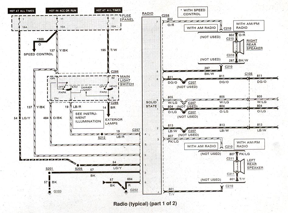
How the 1994 Ford Ranger Stereo Wiring Works
The '94 Ranger's audio system is relatively straightforward. The head unit receives power from the vehicle's electrical system – a constant 12V source for memory and a switched 12V source that turns the unit on and off with the ignition. The head unit then processes the audio signal from the radio antenna or cassette player and amplifies it. This amplified signal is then sent to the speakers via the wiring harness.
Each speaker has two wires: a positive (+) and a negative (-) wire. The head unit sends the audio signal through these wires to the speaker, causing the speaker cone to vibrate and produce sound. Getting the polarity correct is important – reversing the polarity on one speaker can negatively affect the sound quality (specifically the bass response).
Real-World Use and Basic Troubleshooting Tips
Here are some practical troubleshooting scenarios where the wiring diagram becomes your best friend:
- No Power to the Head Unit: Use the diagram to trace the 12V constant and switched power wires. Check the fuses associated with the radio. Use a multimeter to verify that power is reaching the head unit.
- Speaker Not Working: Check the speaker wiring for any breaks or loose connections. Use a multimeter to test the speaker for continuity. Try swapping the speaker with a known good one to rule out a faulty speaker.
- Distorted Sound: Could be a sign of a damaged speaker, a short in the speaker wiring, or a problem with the head unit. Check the speaker wiring for any signs of damage or corrosion.
- Aftermarket Head Unit Installation Issues: Ensure you are using the correct wiring harness adapter. Double-check all connections against the diagram. Verify that the adapter's wires are correctly matched to the head unit's wires.
Safety Considerations
Working with automotive electrical systems can be dangerous. Always take the following precautions:
- Disconnect the Battery: Before working on any wiring, disconnect the negative terminal of the battery to prevent shorts and electrical shocks. This is absolutely essential!
- Use Proper Tools: Use insulated tools designed for automotive electrical work.
- Avoid Water: Never work on electrical systems in wet conditions.
- Check Fuses: Always check and replace blown fuses with the correct amperage rating. Using a higher amperage fuse can damage the electrical system.
- Identify Wires Correctly: Never assume a wire's function based solely on its color. Always verify with the wiring diagram and a multimeter.
Important: Working with electrical systems can be hazardous. If you are not comfortable performing these tasks, consult a qualified automotive electrician.
We have the complete 1994 Ford Ranger Stereo Wiring Diagram available for download. This detailed diagram will provide you with the visual aid you need to confidently navigate the wiring and tackle your audio system projects.