96 Cherokee 1996 Jeep Cherokee Fuse Box Diagram
Alright, let's dive into the fuse box diagram for your 1996 Jeep Cherokee (XJ). If you're like me, you value understanding how your ride ticks, and a fuse box diagram is absolutely crucial for troubleshooting electrical gremlins, planning modifications, or just general maintenance. It's your roadmap to the XJ's nervous system. Think of it as the legend to your electrical treasure map!
Purpose of the Fuse Box Diagram
The 1996 Cherokee fuse box diagram serves a few key purposes. Primarily, it's your go-to resource for identifying and replacing blown fuses. A blown fuse is often the first sign of an electrical problem. Without the diagram, you're basically guessing which fuse controls which component. Beyond simple replacement, it's invaluable for:
- Troubleshooting: Tracing circuits to diagnose electrical issues. For instance, if your windshield wipers aren't working, the diagram will tell you which fuse to check.
- Modifications: If you're adding aftermarket accessories (lights, stereos, etc.), the diagram helps you find suitable circuits to tap into, ensuring you don't overload the system.
- Learning: Understanding the electrical layout of your XJ. The more you know, the better equipped you are to keep it running smoothly.
- Documentation: Keeping a copy of the diagram handy means you always have the information you need, even if you're out on the trail.
Key Specs and Main Parts
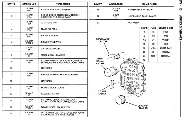
The 1996 Cherokee typically has two fuse boxes: one located under the dashboard, often on the driver's side, and another in the engine compartment (also called the Power Distribution Center). We will mainly focus on the one under the dashboard because it covers the most common circuits you'll encounter. The diagram provides the following key information:
- Fuse Number: Each fuse slot is numbered (e.g., Fuse #1, Fuse #2, etc.). The diagram identifies what each fuse number protects.
- Fuse Amperage: The amperage rating (e.g., 10A, 15A, 20A) indicates the maximum current the fuse can handle before blowing. Using a fuse with a higher amperage than specified can damage the circuit and potentially cause a fire.
- Circuit Description: A brief description of the circuit protected by each fuse (e.g., "Radio," "Cigarette Lighter," "Headlights").
Main Components Shown in Diagram
- Fuses: The obvious ones! Different amperage ratings are essential for circuit protection.
- Relays: Electrically operated switches that control higher-current circuits. Relays are usually in the Power Distribution Center. The diagram might not explicitly show them in the interior fuse box diagram, but it can point to which relays are related to the fuses you are checking.
- Circuit Breakers: Some circuits use circuit breakers instead of fuses. These automatically reset after a short period of time once the overload is removed. The diagram will specify if a circuit uses a breaker.
Symbols: Understanding the Language
Fuse box diagrams use standardized symbols and conventions to represent different components and circuits. Here's a breakdown of the common ones:
- Lines: Lines represent electrical wires or circuits. Thicker lines often indicate higher-current circuits.
- Colors: Wire colors are crucial for tracing circuits in the real world. The diagram will usually indicate the wire color associated with each fuse. For example, "Red/White" would mean a red wire with a white stripe.
- Icons:
- Fuse Symbol: Typically a rectangular shape with a zigzag line through it.
- Relay Symbol: A square or rectangle with a coil symbol and a switch symbol.
- Ground Symbol: Resembles an upside-down Christmas tree, indicating a connection to the vehicle's chassis ground.
Pay close attention to the legend or key that accompanies the diagram. This explains any non-standard symbols used in that specific diagram.
How It Works: The Electrical Flow
Understanding how the electrical system works is key to using the fuse box diagram effectively. Here's the basic flow:
- Power Source: The battery provides the initial power.
- Ignition Switch: The ignition switch controls the flow of power to various circuits depending on its position (OFF, ACC, ON, START).
- Fuse Box: The fuse box distributes power to different circuits, with each fuse protecting a specific component or group of components.
- Circuit: The circuit carries power to the device it's designed to operate (e.g., a light bulb, a motor, a sensor).
- Ground: The circuit returns to the battery's negative terminal through a ground connection.
If a circuit draws too much current (due to a short circuit, a faulty component, or an overloaded circuit), the fuse blows, interrupting the flow of electricity and preventing damage to the system. The fuse acts as a sacrificial element, protecting the more expensive and critical components.
Real-World Use: Basic Troubleshooting
Let's say your turn signals aren't working. Here's how you'd use the fuse box diagram:
- Consult the Diagram: Locate the fuse labeled "Turn Signals" (or something similar). Note the fuse number and amperage rating.
- Locate the Fuse: Find the corresponding fuse in the fuse box.
- Inspect the Fuse: Visually inspect the fuse. A blown fuse will have a broken filament or a dark, burnt appearance.
- Test the Fuse: For a more accurate check, use a multimeter to test for continuity across the fuse terminals. A good fuse will show continuity (close to 0 ohms).
- Replace the Fuse: If the fuse is blown, replace it with a new fuse of the exact same amperage rating.
- Test the Circuit: After replacing the fuse, test the turn signals to see if they now work.
If the fuse blows again immediately, there's a problem in the circuit that needs further investigation. Don't just keep replacing fuses with higher amperage ones – that's a recipe for disaster!
Safety First: Risky Components
When working with electrical systems, safety is paramount. Here are some key safety considerations:
- Disconnect the Battery: Before working on any electrical component, disconnect the negative battery cable. This prevents accidental shorts and shocks.
- Use the Correct Fuse: Always replace a blown fuse with a fuse of the same amperage rating. Using a higher amperage fuse can overload the circuit and cause a fire.
- Avoid Water: Never work on electrical systems in wet conditions.
- Be Careful with Wires: Inspect wires for damage (fraying, cracking, exposed conductors). Damaged wires can cause short circuits.
- Don't Overload Circuits: When adding aftermarket accessories, make sure you're not overloading the circuit. Use a multimeter to measure the current draw and compare it to the fuse rating.
Pay special attention to circuits related to the fuel system, airbags, and ABS. These are critical safety systems, and improper handling can have serious consequences. If you're not comfortable working on these systems, it's best to consult a qualified mechanic.
Remember, electrical problems can be tricky to diagnose. Take your time, be methodical, and use the fuse box diagram as your guide. You might be surprised at how much you can accomplish with a little knowledge and patience.
Now you are ready to tackle your jeep, we have the full 1996 Jeep Cherokee Fuse Box Diagram available for download. This comprehensive resource will provide you with a detailed visual guide, making your electrical troubleshooting and maintenance tasks significantly easier.