
97 Dodge Ram 1500 Radio Wiring Diagram
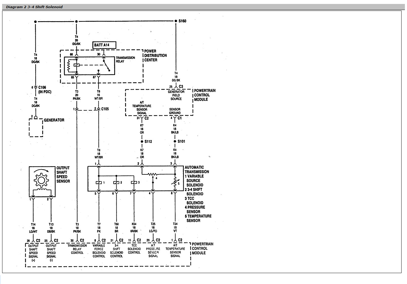
Let's dive into the wiring of the radio in a 1997 Dodge Ram 1500. Understanding this wiring diagram is crucial whether you're replacing a malfunctioning radio, upgrading to a modern head unit, adding aftermarket speakers, or simply troubleshooting audio problems. This guide will walk you through the essential elements, symbols, and real-world applications of the diagram, empowering you to work confidently and safely on your truck's audio system.
Purpose of Understanding the Radio Wiring Diagram
Why bother learning about the wiring diagram? Well, the diagram serves several vital purposes:
- Radio Replacement/Upgrade: This is probably the most common reason. Swapping out the factory radio with an aftermarket one requires understanding which wires power the unit, provide ground, connect to the speakers, and handle other functions like illumination and power antenna control.
- Speaker Installation: Adding or replacing speakers demands correct wiring to ensure proper impedance matching (more on that later) and prevent damage to your radio's amplifier.
- Troubleshooting Audio Issues: A wiring diagram allows you to trace circuits and identify potential problems like shorts, opens, or faulty connections. It’s essential for pinpointing the source of issues like no sound, distorted audio, or a radio that won't turn on.
- Security System Integration: Connecting aftermarket security systems or remote starters often involves tapping into the radio's wiring for features like muting the audio during an alarm event.
- Learning and Understanding: Even if you don't plan on modifying your radio system, understanding the wiring diagram provides a fundamental knowledge of automotive electrical systems, which can be beneficial for tackling other vehicle repairs.
Key Specs and Main Parts
Before we delve into the diagram itself, let's familiarize ourselves with the key components and specifications relevant to the '97 Ram 1500's radio wiring:
- Operating Voltage: The radio operates on the vehicle's standard 12V DC electrical system.
- Speaker Impedance: The factory speakers typically have an impedance of 4 ohms. It's crucial to match the impedance of any replacement speakers to avoid overloading the radio's amplifier. Using speakers with too low of an impedance can damage the amplifier, while using speakers with too high of an impedance may result in lower volume output.
- Radio Chassis Ground: The radio chassis must be properly grounded to the vehicle's body for proper operation. A poor ground can cause noise, distortion, or intermittent radio operation.
- Constant 12V (Memory Wire): This wire provides constant power to the radio, even when the ignition is off. It allows the radio to retain memory settings such as preset stations and clock settings.
- Switched 12V (Ignition Wire): This wire provides power to the radio only when the ignition is turned on. It's typically connected to an accessory circuit in the ignition switch.
- Speaker Outputs: These wires connect to the individual speakers in the vehicle. The diagram will typically show the positive (+) and negative (-) connections for each speaker.
- Antenna Input: This connector receives the radio signal from the vehicle's antenna.
- Optional Features: Depending on the specific trim level, the radio may also have connections for features like a power antenna, amplifier turn-on lead, or CD changer control.
Understanding the Symbols in the Wiring Diagram
Wiring diagrams use a standardized set of symbols to represent electrical components and connections. Here's a breakdown of the most common symbols you'll encounter in the '97 Ram 1500 radio wiring diagram:
- Solid Lines: Indicate wires connecting different components. The thickness of the line doesn't usually represent wire gauge.
- Dashed Lines: May indicate shielded wiring or wiring that is part of a larger harness.
- Circles: Represent connectors or terminals where wires are joined.
- Rectangles: Often represent components such as the radio head unit, amplifiers, or other electronic modules.
- Ground Symbol (⏚): Indicates a connection to the vehicle's chassis ground.
- Battery Symbol (+/-): Represents the vehicle's battery and the positive and negative terminals.
- Fuses: Shown as a wavy line within a rectangle or a small rectangle with a diagonal line through it.
- Color Codes: Wires are identified by color codes, such as RD (red), BL (blue), BK (black), WT (white), GN (green), YL (yellow), OR (orange), and VT (violet). These codes are crucial for identifying the correct wires during installation or troubleshooting. Often the color code will include a second color for a stripe, for example, WT/BK would be a white wire with a black stripe.
The wiring diagram will also include abbreviations and numerical designations for circuits and connectors. Carefully study the legend or key provided with the diagram to understand the meaning of each symbol and abbreviation.
How It Works: The Radio Circuit
The radio circuit is relatively straightforward. The constant 12V wire provides continuous power to maintain memory functions. The switched 12V wire activates the radio when the ignition is on. The ground wire provides a return path for the current. Speaker wires carry the amplified audio signal to the speakers. The antenna wire brings in the radio signal.
When you turn the ignition on, the switched 12V wire provides power to the radio's main power supply. This activates the radio's internal circuitry, including the amplifier and tuner. The tuner receives the radio signal from the antenna and decodes the audio information. The amplifier boosts the audio signal and sends it to the speakers via the speaker wires.
The constant 12V wire ensures that the radio retains its memory settings, such as preset stations and clock settings, even when the ignition is off.
Real-World Use: Basic Troubleshooting Tips
Here are a few common issues and how the wiring diagram can help you diagnose them:
- No Power to Radio: Check the fuses related to the radio circuit using the wiring diagram to locate them. Use a multimeter to verify that the constant and switched 12V wires are receiving power. Also, ensure the ground connection is secure and free of corrosion.
- No Sound: Verify the speaker connections at both the radio and the speakers. Use a multimeter to check for continuity in the speaker wires. You can also try swapping the left and right speaker connections to see if the problem moves to the other side, indicating a faulty speaker.
- Distorted Sound: This could be caused by a faulty speaker, a problem with the radio's amplifier, or incorrect speaker impedance. Check the speaker impedance and compare it to the radio's specifications. Inspect the speakers for damage or wear.
- Intermittent Radio Operation: This could be caused by loose connections, corrosion, or a faulty ignition switch. Carefully inspect all wiring connections and connectors for damage or corrosion. Use a multimeter to check for voltage drops in the power and ground circuits.
- Radio Won't Turn Off: This usually indicates a problem with the ignition switch or the switched 12V wire. Check the ignition switch for proper operation. Use a multimeter to verify that the switched 12V wire is turning off when the ignition is turned off.
Safety Considerations
Working with automotive electrical systems can be dangerous. Always take the following precautions:
- Disconnect the Battery: Before working on any electrical components, disconnect the negative terminal of the battery to prevent shorts and electrical shocks.
- Use a Multimeter: A multimeter is an essential tool for diagnosing electrical problems. Learn how to use it safely and effectively.
- Avoid Working in Wet Conditions: Water can conduct electricity and increase the risk of electrical shock.
- Protect Wires: When running new wires, protect them from sharp edges and heat sources. Use wire loom or electrical tape to insulate and protect the wires.
- Be Careful with Airbags: Never probe or tamper with airbag wiring. Accidental airbag deployment can cause serious injury.
Remember that working on your car's electrical system involves inherent risks. If you are not comfortable with electrical work, it's best to consult a qualified mechanic.
Now that you have a solid foundation in understanding the '97 Dodge Ram 1500 radio wiring diagram, you're better equipped to tackle audio system repairs and upgrades. This knowledge empowers you to diagnose problems, install new equipment, and enjoy your truck's audio system to the fullest.
Ready to dive deeper? We have the complete 1997 Dodge Ram 1500 radio wiring diagram available for download. This detailed document will provide you with the exact wire colors, connector locations, and circuit information you need for your project. Use it wisely, and work safely!