97 Expedition 1997 Ford Expedition Fuse Box Diagram
For the experienced DIYer tackling electrical issues in a 1997 Ford Expedition, a reliable fuse box diagram is absolutely essential. Think of it as the Rosetta Stone for your vehicle's electrical system. Without it, you're essentially working blind, guessing which fuse controls which circuit. This article will walk you through the nuances of your 1997 Expedition's fuse box diagram, empowering you to diagnose and repair electrical problems with confidence.
Purpose of the Fuse Box Diagram
The fuse box diagram serves several critical purposes:
- Troubleshooting Electrical Problems: When a circuit fails (lights don't work, radio goes dead, etc.), the diagram helps you pinpoint the corresponding fuse to check.
- Identifying Circuit Function: The diagram clearly labels what each fuse and relay protects. This is crucial for understanding how your vehicle's electrical system is organized.
- Safe Modifications: If you're adding aftermarket accessories (lights, stereo, etc.), the diagram helps you locate appropriate power sources and avoid overloading existing circuits. Overloading circuits is a sure way to cause a fire or permanent damage.
- Preventing Damage: Replacing a blown fuse with one of a higher amperage *without* consulting the diagram can cause serious damage to wiring and components. This is a cardinal sin in automotive electrical work!
- Learning: Studying the diagram enhances your overall understanding of automotive electrical systems.
Key Specs and Main Parts
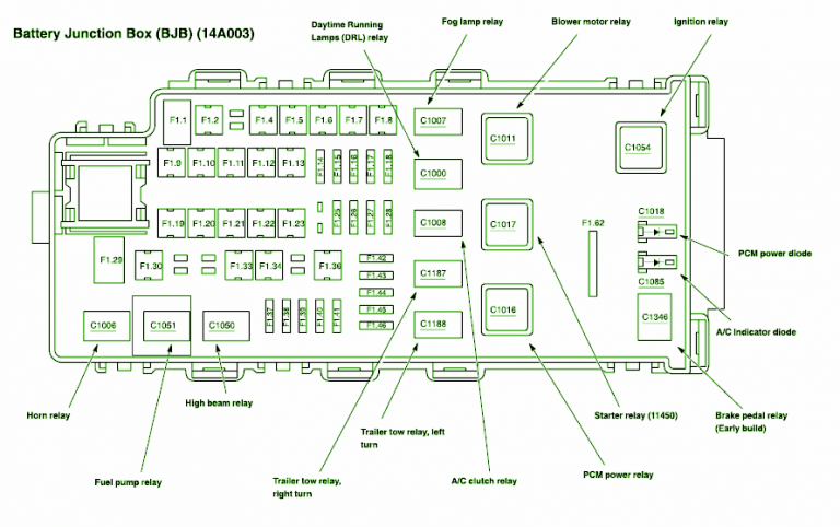
The 1997 Ford Expedition has two main fuse boxes. The primary one is located under the dashboard, typically on the driver's side. The secondary fuse box, often referred to as the power distribution box, is located under the hood, usually near the engine compartment. Each box has its own diagram. Here's what you can expect to find:
- Fuses: These are sacrificial devices designed to protect circuits from overcurrent. They come in various amperage ratings (e.g., 5A, 10A, 15A, 20A, 25A, 30A). The amperage rating is usually printed on the fuse itself.
- Relays: Relays are electrically operated switches. They allow a low-current circuit to control a high-current circuit. For example, the headlight circuit might use a relay. This keeps the high current draw of the headlights from flowing through the headlight switch itself, preventing premature wear and tear.
- Circuit Breakers: Some circuits use circuit breakers instead of fuses. Unlike fuses, circuit breakers can be reset after tripping. They are often used for high-current applications like power windows or door locks.
- Grounding Points: These are connection points where electrical circuits are grounded to the vehicle's chassis. Good grounding is critical for proper electrical system operation.
- Diagram Legend: The diagram will have a legend explaining the symbols and abbreviations used. This is crucial for accurate interpretation.
Symbols – Understanding the Diagram's Language
The fuse box diagram uses specific symbols to represent different components and connections. Here's a breakdown of common symbols:
- Lines: Lines represent wires. The thickness of the line does *not* typically indicate wire gauge.
- Boxes: Boxes usually represent fuses or relays. The amperage rating of a fuse is often indicated within or next to the box.
- Circles: Circles can represent various components, depending on the context. Check the diagram's legend.
- Ground Symbol: This symbol (often resembling a tree or an upside-down triangle) indicates a ground connection.
- Colors: While the diagram itself may not be in color, wiring diagrams often use color codes to identify wires. The 1997 Expedition wiring can be challenging as Ford used a variety of colors and stripe combinations. Knowing the specific color code for your vehicle (found in a separate wiring diagram) is extremely helpful.
- Abbreviations: The diagram will use abbreviations to describe the function of each fuse or relay (e.g., "IGN" for ignition, "PCM" for Powertrain Control Module, "EEC" for Electronic Engine Control).
The lines that visually connect each fuse/relay to the name or abbreviation is the important part. You need to find the fuse or relay with the specific name that you're looking for, in order to troubleshoot your vehicle.
How It Works – The Electrical Flow
Understanding the basic flow of electricity through a circuit is key to using the fuse box diagram effectively. Electricity flows from the battery, through a fuse or circuit breaker (for protection), through the circuit components (e.g., lights, motors), and back to the battery through a ground connection. The fuse is the weak point in the circuit. If the current exceeds the fuse's amperage rating, the fuse blows, breaking the circuit and preventing damage to the components.
Relays act as intermediaries. A small current flows through the relay coil, energizing it and causing the relay contacts to close, which then allows a larger current to flow through the main circuit.
Real-World Use – Basic Troubleshooting Tips
Here's how to use the fuse box diagram to troubleshoot common electrical problems:
- Identify the Problem: Determine which circuit is malfunctioning (e.g., headlights, radio, power windows).
- Consult the Diagram: Locate the corresponding fuse or relay for that circuit on the diagram. Refer to *both* the under-dash and under-hood fuse box diagrams.
- Check the Fuse: Visually inspect the fuse. A blown fuse will have a broken filament inside. You can also use a multimeter to test continuity. Set the multimeter to the continuity setting (usually indicated by a diode symbol or a sound wave symbol). Place the probes on either side of the fuse. If the multimeter beeps or shows a reading close to zero, the fuse is good. If it shows an open circuit (no continuity), the fuse is blown.
- Check the Relay: Relays can be tested using a multimeter, but it's a bit more complex. You can also try swapping the relay with a known good relay of the same type to see if that resolves the issue.
- Replace the Fuse: If the fuse is blown, replace it with a new fuse of the *same* amperage rating. Never use a fuse with a higher amperage rating!
- If the Fuse Blows Again: If the new fuse blows immediately, there's a short circuit in the wiring or a faulty component in the circuit. Further diagnostics are required, including inspecting the wiring for damage and testing the components.
Safety – Handle with Care
Working with automotive electrical systems can be dangerous. Here are some key safety precautions:
- Disconnect the Battery: Before working on any electrical components, disconnect the negative battery cable. This prevents accidental shorts and electrical shocks.
- Identify Risky Components: The starting system, charging system (alternator), and ignition system involve high voltages and currents. Be extra careful when working on these systems.
- Use Insulated Tools: Use tools with insulated handles to prevent electrical shocks.
- Wear Safety Glasses: Protect your eyes from sparks and debris.
- Never Probe Live Wires: Unless you are experienced and using the proper equipment, avoid probing live wires.
- Don't Work Alone: It's always a good idea to have someone else present when working on electrical systems.
Remember: If you're uncomfortable working on electrical systems, consult a qualified mechanic. Electrical problems can be complex, and improper repairs can cause further damage or even create a fire hazard.
Important: Replacing fuses with higher amperage ratings is extremely dangerous. It can bypass the intended protection and cause wires to overheat, potentially leading to a fire. Always use the correct amperage rating specified in the fuse box diagram.
With a solid understanding of your 1997 Ford Expedition's fuse box diagram and the fundamental principles of automotive electrical systems, you'll be well-equipped to tackle many common electrical repairs and modifications. Remember to prioritize safety and consult a professional if you're unsure about any aspect of the work.
We have a high-resolution, downloadable PDF of the 1997 Ford Expedition Fuse Box Diagram available for your convenience. Access this valuable resource to get a clear visual guide to your vehicle's electrical system. Having this at your fingertips will make troubleshooting and repair tasks much more efficient.