97 Honda Civic Stereo Wiring Diagram
Working on a 1997 Honda Civic's stereo system? Whether you're replacing a blown speaker, upgrading to a modern head unit, or simply trying to diagnose a wiring issue, understanding the stereo wiring diagram is absolutely crucial. This isn't just about getting music; it's about the safe and proper functioning of your car's electrical system. Having access to and understanding the wiring diagram prevents accidental shorts, blown fuses, and potential damage to sensitive electronics. In this article, we'll break down the key components of the '97 Civic's stereo wiring, explain the common symbols and color codes, and provide practical troubleshooting tips. We have the full diagram available for download to further assist you!
Purpose of the Wiring Diagram
The primary purpose of a stereo wiring diagram is to provide a visual representation of how all the components of the audio system are interconnected. This includes the head unit (radio/CD player), speakers, amplifier (if equipped), antenna, and various power and ground connections. Knowing the function of each wire and how it's connected allows you to:
- Diagnose problems: Pinpoint the source of a problem like a dead speaker, no power to the radio, or distorted sound.
- Install aftermarket components: Properly connect a new head unit, amplifier, or subwoofer without damaging the factory wiring.
- Repair damaged wiring: Identify broken or corroded wires and repair or replace them correctly.
- Understand the system: Gain a deeper understanding of how the car's audio system functions, enabling more informed modifications and upgrades.
Key Specs and Main Parts
The 1997 Honda Civic's factory stereo system is relatively straightforward, but understanding the key components is still important. Here's a breakdown:
- Head Unit: This is the central control unit, typically a radio/CD player combination. It provides the user interface, processes audio signals, and sends power to the speakers.
- Speakers: The Civic typically has speakers in the front doors and sometimes in the rear deck or doors, depending on the trim level (e.g., DX, LX, EX). The impedance of these speakers is usually 4 ohms.
- Wiring Harness: This is a connector that plugs into the back of the head unit, providing all the necessary connections for power, ground, speakers, and other functions.
- Antenna: Receives radio signals. The '97 Civic uses a standard antenna connection.
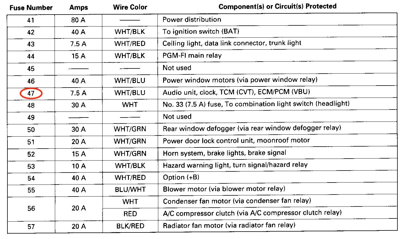
- Fuses: Protect the stereo system from overloads. The main fuse for the stereo is located in the interior fuse box.
Important specifications to note are the voltage (12V DC), speaker impedance (typically 4 ohms), and the current rating of the fuses protecting the circuit.
Understanding the Symbols
Wiring diagrams use standardized symbols to represent different components and connections. Here's a guide to some common symbols you'll encounter in the '97 Civic stereo wiring diagram:
- Solid Lines: Represent wires connecting different components. The thickness of the line *doesn't* usually indicate wire gauge.
- Dashed Lines: May represent shielding or connections that are only present in certain trim levels.
- Circles/Dots: Indicate a connection point where wires are joined.
- Rectangles: Often represent electronic components like the head unit or amplifier.
- Speaker Symbol: A stylized representation of a speaker cone.
- Ground Symbol: A symbol that looks like a downward-pointing arrow with parallel lines. It indicates a connection to the vehicle's chassis ground.
- Fuse Symbol: Represents a fuse, often depicted as a wavy line inside a rectangle.
Color Codes: Wire colors are crucial for identification. The '97 Civic uses a standard color coding system. Some common colors you'll encounter include:
- Red: Usually indicates a constant 12V power supply.
- Yellow: Often indicates a switched 12V power supply (power when the ignition is on).
- Black: Indicates ground.
- White: Commonly used for speaker wires.
- Other colors (e.g., Blue, Green, Brown, Purple): Used for specific functions, often for speaker wires or control signals. Refer to the wiring diagram's legend to confirm the function of each color.
Remember that wire colors can fade or change over time due to heat and exposure, so always verify the wire's function with a multimeter if you're unsure.
How It Works
The stereo system's operation is fairly simple. The head unit receives power from the car's battery (through the constant 12V wire) and a switched source (through the ignition switch). When the ignition is turned on, the head unit powers up. The head unit then processes audio signals from either the radio antenna or the CD player, amplifies them, and sends them to the speakers. The speakers convert the electrical signals into sound waves.
Ground connections are essential for completing the circuit. A good ground connection ensures proper operation and prevents noise or distortion.
Real-World Use: Basic Troubleshooting Tips
Here are some common stereo problems and how the wiring diagram can help you troubleshoot them:
- No Power to Head Unit: Check the fuses first. Use a multimeter to verify that the constant 12V and switched 12V wires are receiving power. If not, trace the wires back to the fuse box and ignition switch to identify the break. Also, verify a good ground connection.
- One Speaker Not Working: Check the speaker wiring for breaks or loose connections. Use a multimeter to test the speaker's continuity. If the wiring and speaker are good, the problem might be with the head unit's amplifier.
- Distorted Sound: Could be a sign of a damaged speaker, a bad ground connection, or a problem with the head unit's amplifier. Inspect the speaker cone for damage and check the wiring for corrosion.
- Radio Not Receiving Signal: Check the antenna connection at the head unit. Inspect the antenna wire for breaks or damage. If possible, test the antenna with another radio.
When troubleshooting, always disconnect the battery's negative terminal to prevent accidental shorts.
Safety Considerations
Working with automotive electrical systems can be dangerous. Here are some safety precautions:
- Disconnect the Battery: Always disconnect the negative terminal of the battery before working on any electrical component. This prevents accidental shorts and potential damage to the car's electrical system.
- Fuses are Crucial: Never bypass a fuse with a wire or a higher-rated fuse. Fuses are designed to protect the wiring and components from overloads. Using the incorrect fuse can lead to a fire.
- Airbags: Be extremely careful when working near airbags. Disconnect the battery and wait at least 10 minutes before working near airbags to allow the system to discharge. Refer to the vehicle's service manual for specific airbag safety procedures.
- Wiring Integrity: Always use proper wiring techniques. Use crimp connectors or solder to join wires. Wrap exposed wires with electrical tape. Ensure that wires are properly routed and secured to prevent chafing or damage.
The constant 12V wire is always live, even with the ignition off. Be extremely cautious when working with this wire.
By understanding the 1997 Honda Civic stereo wiring diagram and following these safety precautions, you can confidently tackle a variety of audio system projects. Having the right information and tools will ensure a successful and safe outcome. We have the complete wiring diagram available for download – click the link below to access it!
[Download Link Placeholder]