97 Toyota Camry Radio Wiring Diagram
Alright, let's dive into the 97 Toyota Camry radio wiring diagram. This document might seem like a chaotic mess of lines and symbols at first glance, but understanding it is crucial for a few reasons. Whether you're troubleshooting a dead radio, upgrading your sound system, or just trying to diagnose an electrical gremlin, this diagram is your roadmap. Think of it as the Rosetta Stone for your Camry's audio system. We have the wiring diagram file available for download, which will be an invaluable asset as we go through this.
Purpose of the Diagram
Why bother with a wiring diagram? The most common use is for repairs. Radios fail, wires get damaged, and sometimes you just want to replace the factory unit with something newer. The diagram allows you to identify the correct wires for power, ground, speakers, and any other functions (like an antenna amplifier) your radio might have.
Beyond repairs, the diagram is essential for upgrades. Planning to install a new amplifier, subwoofer, or head unit? Knowing the existing wiring allows you to integrate your new components seamlessly without cutting corners or creating potentially dangerous shorts. Furthermore, understanding the diagram will help you avoid damaging any of the car's existing systems during the upgrade process.
Finally, even if you're not planning any immediate modifications, studying the diagram provides a better understanding of your car's electrical system. This knowledge can be helpful in diagnosing other issues down the road. Knowing how the radio circuit is wired can often point you towards shared grounds or power sources that might be affecting other components.
Key Specs and Main Parts
The 97 Camry radio wiring diagram typically covers the following key components:
- Head Unit (Radio): This is the brain of the operation, containing the tuner, amplifier, and controls. It's where you'll find connections for power, ground, speakers, antenna, and sometimes auxiliary inputs.
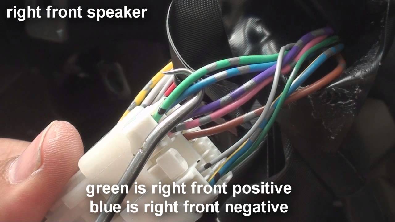
- Speakers: Usually, there are four speakers: front left, front right, rear left, and rear right. The diagram will show the color-coded wires leading to each speaker.
- Antenna: The antenna receives the radio signal. Some Camrys have a power antenna, which requires a separate wire to signal it to extend or retract.
- Power Source: The radio needs a constant 12V power source (usually from the battery) to retain memory (stations, settings) and a switched 12V power source (usually from the ignition switch) to turn on and off.
- Ground: Essential for completing the electrical circuit. The ground wire is usually connected to the car's chassis.
- Fuses: A critical safety component that protects the radio circuit from overcurrent. The diagram will show the location and amperage of the fuse.
Key specifications to note include the wire gauge (thickness) and the voltage of the circuits. The wire gauge determines the amount of current the wire can safely handle, and the voltage, in this case 12V DC, is the electrical potential difference.
Symbols – Deciphering the Diagram
The wiring diagram uses a standardized set of symbols. Here’s a breakdown of the most important ones:
- Solid Lines: Represent wires. Thicker lines usually indicate a higher current carrying capacity.
- Dotted Lines: Often indicate shielded wires or wires related to optional features.
- Color Codes: Wires are identified by color codes. Common colors include Red (power), Black (ground), White (speaker), Blue (antenna), etc. The diagram legend will define each color abbreviation (e.g., "R" for Red, "B" for Black, "W" for White, "L" for Blue, "G" for Green, "Y" for Yellow).
- Ground Symbol: Looks like a series of horizontal lines decreasing in length. This indicates a connection to the vehicle's chassis, which serves as the ground.
- Fuse Symbol: A zigzag line inside a rectangle. The amperage rating of the fuse will be noted next to the symbol.
- Connector Symbol: Rectangles or circles with numbers inside. These represent connectors where wires are joined. The diagram will often show the connector's location in the vehicle.
- Component Symbols: Represent specific parts like the radio, speakers, and antenna. These symbols are usually stylized representations of the actual components.
It’s crucial to pay attention to the color codes. These are the primary way to identify wires. A wire labeled "R/W" would be a red wire with a white stripe.
How It Works
The 97 Camry radio circuit is relatively straightforward. The battery provides a constant 12V power source to the radio through a fuse. This allows the radio to retain its memory settings. When the ignition switch is turned on, a switched 12V power source is also supplied to the radio, turning it on. The radio then amplifies the audio signal from the tuner or an external source (like a CD player) and sends it to the speakers.
The ground wire provides a return path for the electrical current, completing the circuit. The antenna receives radio signals, and some vehicles utilize an antenna amplifier that requires power. This amplifier boosts the signal, especially in areas with weak reception.
The wiring diagram illustrates how all these components are connected. It shows the path of the current from the power source to the radio, through the speakers, and back to ground. By tracing these paths, you can understand how the system works and identify potential points of failure.
Real-World Use – Basic Troubleshooting Tips
Let's say your radio is completely dead. Here’s how you might use the wiring diagram to troubleshoot:
- Check the Fuse: Locate the fuse for the radio (the diagram will show its location in the fuse box). Use a multimeter to check for continuity. If the fuse is blown, replace it with a fuse of the correct amperage. Important: Repeatedly blowing fuses indicates a short circuit, which needs to be investigated further.
- Check Power and Ground: Use a multimeter to check for 12V power at the radio connector. Make sure you have both the constant and switched power sources present. Also, check the ground connection for continuity to the chassis. A poor ground connection can cause all sorts of problems.
- Inspect the Wiring: Visually inspect the wiring harness for any signs of damage, such as frayed wires, corroded connectors, or loose connections. Pay close attention to areas where the wiring might be exposed to friction or heat.
If you're upgrading your head unit, the diagram helps you identify the correct wires to connect to your new unit. Most aftermarket head units come with a wiring harness that uses industry-standard color codes. The diagram allows you to match the wires from your car's harness to the wires on the aftermarket harness, ensuring a proper connection.
Pro Tip: Always disconnect the negative terminal of the battery before working on any electrical components. This will prevent accidental shorts and potential damage to your car's electrical system.
Safety – Highlight Risky Components
Working with car electrical systems can be dangerous if you're not careful. Here are some safety precautions:
- Airbags: Be extremely cautious when working near airbags. Accidentally triggering an airbag can cause serious injury. If you need to disconnect any airbag-related components, follow the manufacturer's instructions carefully.
- Short Circuits: Avoid creating short circuits. A short circuit can damage your car's electrical system and potentially start a fire. Always disconnect the battery before working on any electrical components.
- Incorrect Wiring: Connecting wires incorrectly can damage your radio or other components. Always double-check the wiring diagram before making any connections.
- Fuses: Never replace a fuse with one of a higher amperage rating. This can overload the circuit and cause a fire.
The battery itself can be dangerous. It contains sulfuric acid, which can cause burns. Wear gloves and eye protection when working near the battery.
Remember, working on your car's electrical system can be complex and potentially dangerous. If you're not comfortable with any of these procedures, it's best to consult a qualified mechanic.
With the 97 Toyota Camry radio wiring diagram in hand (available for download), you're well-equipped to diagnose and repair issues with your car's audio system. Remember to take your time, double-check your work, and always prioritize safety. Good luck!