98 Ford Ranger Stereo Wiring Diagram
Understanding the stereo wiring diagram for your 1998 Ford Ranger is crucial for various tasks, from diagnosing audio problems to upgrading your sound system or even installing aftermarket components. This isn't just about replacing a blown speaker; it's about gaining a deeper understanding of your vehicle's electrical system and ensuring safe and proper connections. Whether you're a seasoned DIY mechanic or a car audio enthusiast looking to expand your knowledge, this guide will provide you with the technical insights you need to confidently navigate the 98 Ranger's audio wiring.
Why This Diagram Matters
The stereo wiring diagram serves as a roadmap for your audio system. It illustrates how the various components, such as the head unit (radio), speakers, antenna, and any optional amplifiers, are interconnected. Without it, you're essentially flying blind when attempting any modifications or repairs. Here’s why having a clear understanding of the diagram is essential:
- Troubleshooting Audio Issues: If your speakers aren't producing sound, the radio isn't powering on, or you're experiencing other audio problems, the wiring diagram helps you pinpoint the source of the issue. You can systematically trace the wiring to identify breaks, shorts, or faulty components.
- Upgrading Your Stereo System: Planning to install a new head unit, amplifier, or speakers? The wiring diagram is indispensable for connecting these components correctly and ensuring compatibility with your existing system. Improper wiring can damage your equipment or even create electrical hazards.
- Installing Aftermarket Accessories: Adding a subwoofer, a backup camera with audio integration, or other accessories requires tapping into the existing audio wiring. The diagram shows you where to make these connections safely and effectively.
- Learning Your Vehicle's Electrical System: Even if you're not planning any immediate modifications, understanding the stereo wiring diagram can provide valuable insights into your vehicle's overall electrical system. This knowledge can be helpful for diagnosing other electrical problems in the future.
Key Specs and Main Parts
The 1998 Ford Ranger stereo system is a relatively straightforward setup, but understanding its key specifications and components is important.
Head Unit (Radio)
The head unit, or radio, is the heart of the system. It provides the user interface, processes audio signals, and distributes power to the speakers. The 98 Ranger typically came with a single-DIN head unit, meaning it occupies a standard-sized space in the dashboard. It accepts power, ground, antenna input, speaker outputs, and sometimes has additional features like CD player control or auxiliary inputs (depending on the specific trim level).
Speakers
The '98 Ranger usually has speakers in the front doors and sometimes in the rear of the cab, depending on the cab configuration (Regular Cab vs. SuperCab). The standard speaker size in the front doors is typically 5x7 inches or 6x8 inches. The impedance (electrical resistance) of the speakers is typically 4 ohms. Understanding the speaker impedance is crucial when replacing speakers or adding an amplifier to avoid damaging the head unit or amplifier.
Wiring Harness
The wiring harness is a collection of wires bundled together that connect the head unit to the vehicle's electrical system and the speakers. The harness typically uses a standardized connector for easy removal and installation of the head unit. Aftermarket wiring harnesses are readily available to facilitate the installation of new head units without cutting the original vehicle wiring.
Antenna
The antenna receives radio signals and feeds them to the head unit. The 98 Ranger typically uses a standard Motorola-type antenna connector. The antenna wire runs from the antenna base to the back of the head unit.
Symbols – Decoding the Diagram
Wiring diagrams use a standardized set of symbols and color codes to represent different components and connections. Understanding these symbols is essential for interpreting the diagram accurately. Here are some common symbols you'll encounter:
- Solid Lines: Represent wires. The thickness of the line might indicate the wire gauge (thickness), though this is less common.
- Dashed Lines: Often indicate shielding, ground connections, or connections that are optional or not present in all models.
- Circles with a Letter Inside: Typically represent connection points or terminals. The letter inside might identify the specific terminal or connector.
- Rectangles: Generally represent components, such as the head unit, speakers, or fuses.
- Ground Symbol: A downward-pointing arrow or a series of horizontal lines decreasing in length represents a ground connection (connection to the vehicle's chassis).
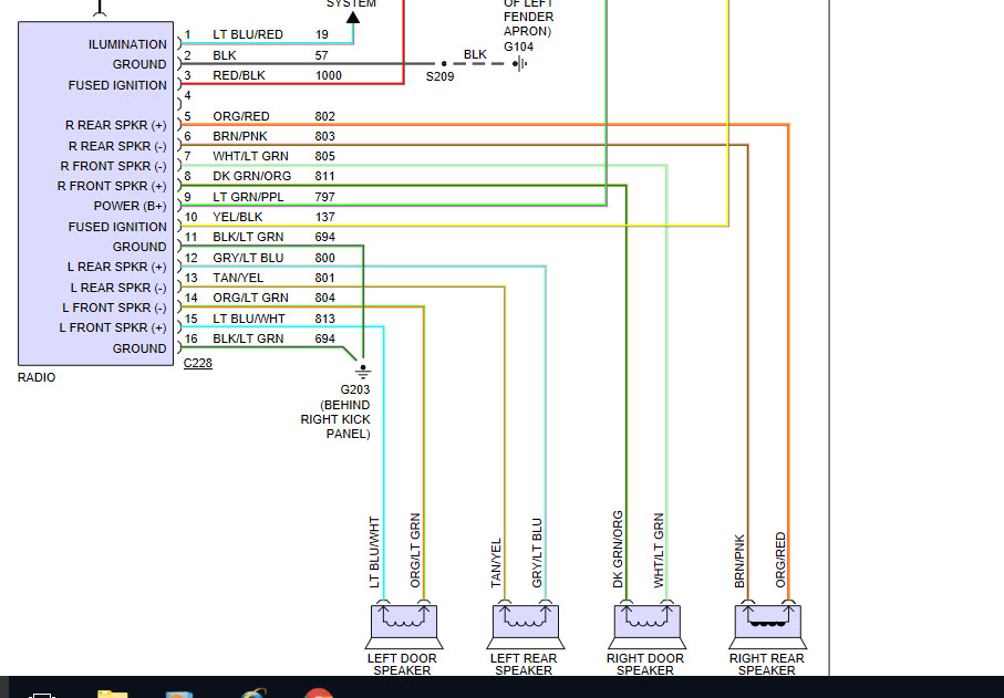
Color Codes: Wires are color-coded to help identify their function. While the specific color codes can vary slightly depending on the trim level and options, here are some common color codes you might encounter in a 1998 Ford Ranger stereo wiring diagram:
- Red: Constant 12V power (battery power)
- Yellow: Switched 12V power (ignition power)
- Black: Ground
- White: Left front speaker (+)
- White/Black: Left front speaker (-)
- Gray: Right front speaker (+)
- Gray/Black: Right front speaker (-)
- Green: Left rear speaker (+)
- Green/Black: Left rear speaker (-)
- Purple: Right rear speaker (+)
- Purple/Black: Right rear speaker (-)
- Blue: Power antenna or amplifier turn-on lead
Always double-check the specific color codes in your diagram, as there may be variations.
How It Works: Signal Flow and Power Distribution
The audio system's operation is relatively straightforward. The head unit receives power from the vehicle's electrical system (constant 12V for memory and switched 12V for operation when the ignition is on). The head unit then processes the audio signal from the radio tuner, CD player, or auxiliary input. This processed signal is then amplified and sent to the speakers via the speaker wires. The speakers convert the electrical signal into sound waves. The antenna receives radio signals and sends them to the head unit for processing.
Real-World Use: Basic Troubleshooting Tips
Here are some basic troubleshooting tips that can be applied using the wiring diagram:
- No Power to the Radio: Check the fuses related to the radio. Use a multimeter to verify that the red (constant 12V) and yellow (switched 12V) wires are receiving power. Also, ensure that the black wire has a good ground connection.
- No Sound from One or More Speakers: Check the speaker wires for breaks or shorts. Use a multimeter to test the speaker wires for continuity (a continuous electrical path). You can also try swapping the left and right speaker wires to see if the problem moves to the other side, which would indicate a faulty speaker.
- Distorted Sound: Check the speaker wiring for shorts or loose connections. A damaged speaker can also cause distorted sound. Make sure the speaker impedance matches the recommended impedance for the head unit or amplifier.
Safety: Handle with Care
Working with automotive electrical systems can be dangerous if proper precautions are not taken. Here are some safety tips:
- Disconnect the Battery: Before working on any electrical components, disconnect the negative terminal of the battery to prevent shorts and electrical shocks.
- Use a Multimeter: A multimeter is an essential tool for diagnosing electrical problems. Learn how to use it to test for voltage, continuity, and resistance.
- Avoid Cutting Wires: Whenever possible, use wiring harnesses or connectors to make connections instead of cutting the original vehicle wiring.
- Proper Insulation: Always use proper electrical tape or heat shrink tubing to insulate any exposed wires to prevent shorts.
- Be Aware of Airbags: Some wiring may run near airbag sensors or modules. Be extremely careful when working in these areas, as accidental deployment of an airbag can cause serious injury. If unsure, consult a professional.
Important: The constant 12V wire is always "hot" (energized) even when the ignition is off. Therefore, disconnecting the battery is paramount before handling these wires.
We have the complete 1998 Ford Ranger Stereo Wiring Diagram file available for download. This detailed diagram will provide you with a comprehensive visual guide to your vehicle's audio system wiring, making troubleshooting, repairs, and upgrades significantly easier.