98 Lincoln Town Car Fuse Box Diagram
The 1998 Lincoln Town Car, a full-size luxury sedan, is known for its smooth ride and robust build. Like any vehicle, its electrical system is the nervous system, controlling everything from the headlights to the engine management. The fuse box diagram is an invaluable tool for diagnosing and rectifying electrical issues in your Town Car. This article will serve as a comprehensive guide to understanding the '98 Town Car's fuse box layout, its components, and how to use it effectively for troubleshooting.
Purpose of Understanding the Fuse Box Diagram
Why bother with the fuse box diagram? The answer is simple: efficient and safe electrical repairs. Attempting to troubleshoot electrical problems without understanding the fuse layout is like navigating a maze blindfolded. The diagram provides a clear roadmap for identifying which fuse controls which circuit. This allows you to:
- Diagnose electrical faults quickly: Pinpoint the exact circuit causing the issue.
- Replace blown fuses safely: Ensure you're using the correct amperage fuse.
- Avoid further damage: Prevent short circuits and potential fires by understanding the electrical system.
- Add aftermarket accessories: Tap into the correct circuits for power without overloading the system.
- Learn your vehicle's electrical system: Gain a deeper understanding of how your car works.
Whether you're a seasoned DIYer or just starting to learn about auto mechanics, understanding your Town Car's fuse box is a foundational skill.
Key Specs and Main Parts
The 1998 Lincoln Town Car has two primary fuse box locations:
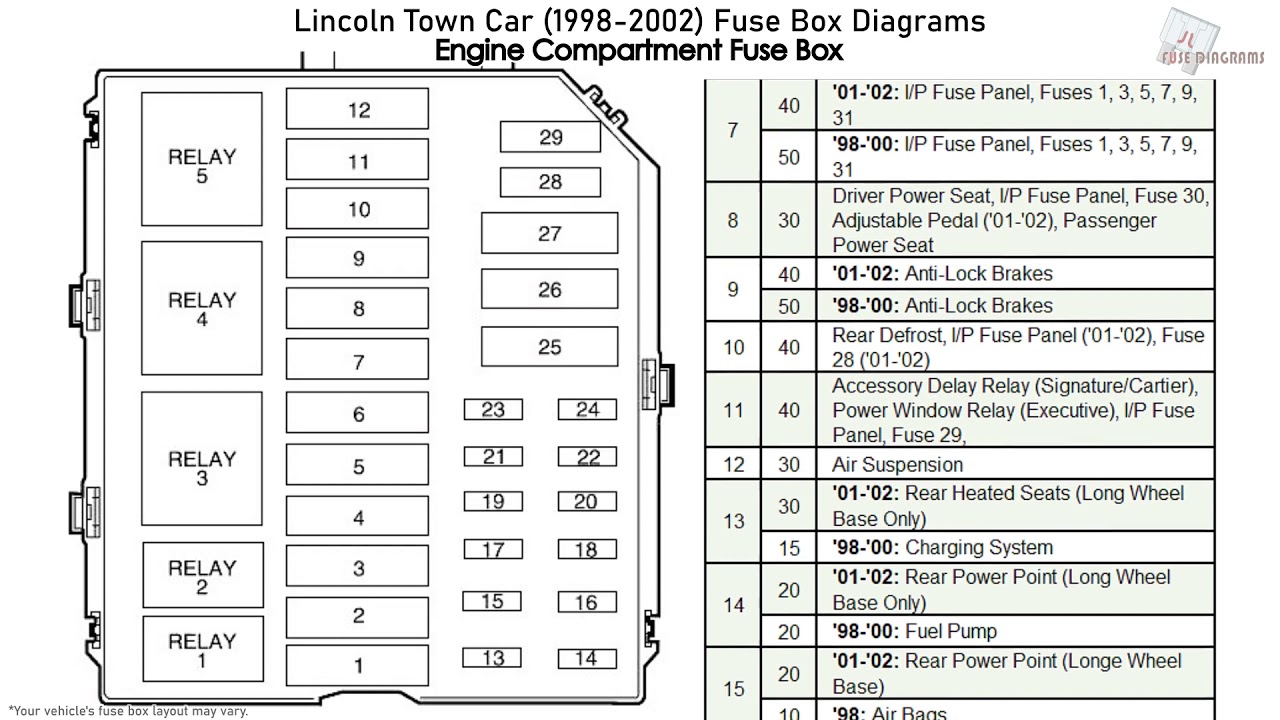
- Under-Hood Fuse Box: Located in the engine compartment, this box houses fuses and relays for high-current components such as the starter motor, fuel pump, cooling fan, and ABS system. It's usually a black, plastic box with a removable cover.
- Interior Fuse Box: Usually found under the dashboard on the driver's side or sometimes on the side panel. This box protects circuits for interior functions like the radio, power windows, power seats, climate control, and lights.
Each fuse box contains:
- Fuses: These are sacrificial devices designed to protect electrical circuits from overcurrent. They consist of a thin wire or strip that melts and breaks the circuit when the current exceeds a certain level. Different amperage ratings (e.g., 5A, 10A, 15A, 20A, 30A) correspond to different current limits.
- Relays: These are electromagnetic switches that allow a low-current circuit to control a high-current circuit. They are used to switch on and off components that require a large amount of power, such as headlights or the starter motor.
- Circuit Breakers: Some circuits may use circuit breakers instead of fuses. Circuit breakers are reusable protection devices that trip and interrupt the circuit when an overcurrent occurs, but they can be reset after the fault is cleared.
- Fuse Puller: A small plastic tool often included in the fuse box, used to safely remove fuses.
The diagram itself is usually printed on the inside of the fuse box cover or located in the owner's manual. It details the location and function of each fuse and relay.
Understanding the Symbols
The fuse box diagram isn't just a jumble of numbers; it's a symbolic representation of the electrical system. Understanding these symbols is critical for accurate troubleshooting. Here's a breakdown of common symbols and conventions:
- Fuse Numbers: Each fuse is assigned a unique number, which corresponds to a specific circuit.
- Amperage Ratings (A): Numbers followed by "A" indicate the fuse's amperage rating (e.g., 15A means 15 Amperes). Using a fuse with the wrong amperage rating can be dangerous. A lower amperage fuse will blow prematurely, while a higher amperage fuse may not protect the circuit adequately, potentially leading to damage or fire.
- Component Icons: Small icons represent the components the fuse protects. These icons can include headlights, windshield wipers, power windows, radio, etc.
- Colors: While not always consistent, some diagrams use colors to differentiate circuits or voltage levels. Consult your specific diagram's legend.
- Lines: Lines on the diagram indicate the electrical connections and pathways. They show how the fuse is connected to the component it protects.
- Relay Symbols: Relays are typically represented by a square or rectangle with internal symbols showing the coil and switch contacts. The diagram will identify which relay controls which component.
Pay close attention to the legend or key that accompanies the diagram. This will explain any specific symbols or conventions used in your '98 Town Car's diagram.
How It Works: The Electrical Circuit Protection
The fuse box is the central distribution and protection point for the vehicle's electrical system. Each fuse protects a specific circuit, which is a closed loop that allows electricity to flow from the battery to a component and back to the battery (through the vehicle's chassis as ground). When a fault occurs, such as a short circuit (a low-resistance path to ground) or an overload (too much current drawn by a component), the current in the circuit increases dramatically.
This excessive current causes the fuse's internal wire to heat up rapidly. When the current exceeds the fuse's amperage rating, the wire melts, breaking the circuit and stopping the flow of electricity. This prevents damage to the wiring, components, and potentially prevents a fire. The fuse acts as a sacrificial element, protecting the rest of the circuit.
Relays, on the other hand, act as remotely controlled switches. A low-current signal from a switch or the car's computer activates the relay, which then closes a high-current circuit to power a component. This allows switches and electronic control units to control high-power devices without having to handle the high current directly, reducing wear and tear on the switches and control units.
Real-World Use: Basic Troubleshooting Tips
Here's how to use the fuse box diagram to troubleshoot common electrical problems:
- Identify the Problem: Determine which component is not working (e.g., the radio, headlights, power windows).
- Locate the Corresponding Fuse: Consult the fuse box diagram to identify the fuse that controls the non-functional component.
- Inspect the Fuse: Remove the fuse using the fuse puller. Visually inspect the fuse. If the wire inside the fuse is broken or blackened, the fuse is blown.
- Replace the Fuse: Replace the blown fuse with a new fuse of the same amperage rating. Never use a fuse with a higher amperage rating.
- Test the Component: Turn on the component to see if it now works.
- If the Fuse Blows Again: If the new fuse blows immediately or shortly after replacement, there is a deeper problem in the circuit, such as a short circuit or a faulty component. Further diagnosis is required. This might involve checking the wiring, connectors, and the component itself.
Important Considerations:
- Keep Spare Fuses: Always keep a selection of spare fuses in your vehicle.
- Use the Correct Fuse: Always use the correct amperage fuse. Using a fuse with a higher amperage rating can damage the wiring or component.
- Inspect the Fuse Box: Check for corrosion, loose connections, or other damage.
- Consult the Owner's Manual: Refer to your owner's manual for specific information about your vehicle's fuse box.
Safety Precautions
Working with electrical systems involves inherent risks. Observe the following safety precautions:
- Disconnect the Battery: Before working on any electrical component, disconnect the negative (-) battery cable to prevent accidental short circuits.
- Use Insulated Tools: Use tools with insulated handles to protect yourself from electric shock.
- Avoid Wet Conditions: Never work on electrical systems in wet or damp conditions.
- Be Aware of High-Voltage Components: The ignition system and other components can carry high voltage even after the car is turned off. Be extremely careful when working near these components. Exercise extreme caution around the airbag system. Improper handling can cause deployment and serious injury. Consult a qualified technician for airbag-related repairs.
- Never Bypass Fuses: Never attempt to bypass a fuse by using a piece of wire or other conductive material. This can create a dangerous situation and cause serious damage.
Remember, if you are not comfortable working with electrical systems, consult a qualified mechanic.
With this guide and access to the '98 Lincoln Town Car fuse box diagram, you'll be better equipped to diagnose and repair electrical issues in your vehicle. The diagram empowers you to understand and maintain your vehicle's electrical system, saving you time and money on repairs.
We have the complete '98 Lincoln Town Car fuse box diagram readily available for download. This detailed diagram will provide you with the exact location and function of each fuse and relay, ensuring accurate troubleshooting.