99 Explorer 1999 Ford Explorer Fuse Box Diagram
Alright, let's dive into the 1999 Ford Explorer fuse box diagram. Understanding this layout is crucial whether you're troubleshooting electrical issues, planning modifications, or simply want a better grasp of your vehicle's inner workings. Think of the fuse box diagram as the Rosetta Stone for your Explorer's electrical system. This guide will break it down in a way that's both technically accurate and easy to understand for the experienced DIYer.
Purpose of the Fuse Box Diagram
Why bother with a fuse box diagram? Simple: it's indispensable for a few key reasons:
- Troubleshooting Electrical Issues: If a circuit fails (e.g., your headlights stop working or your radio goes silent), the first place to check is the fuse box. The diagram identifies the fuse responsible for that circuit, allowing you to quickly diagnose a blown fuse.
- Performing Repairs: Need to replace a component? Knowing which fuse protects that circuit prevents accidental shorts and further damage.
- Planning Modifications: Adding aftermarket accessories (lights, amplifiers, etc.) requires tapping into existing circuits. The diagram helps you identify appropriate circuits and select the correct fuse amperage to avoid overloading the system.
- Understanding Your Vehicle: Even without immediate problems, understanding the fuse layout provides valuable insight into your Explorer's electrical architecture.
Key Specs and Main Parts of the '99 Explorer Fuse System
The 1999 Ford Explorer typically has two main fuse boxes:
- Interior Fuse Box (Passenger Compartment): Located under the dashboard, usually on the driver's side near the steering column. This box houses fuses and relays for interior components like lights, the radio, power windows, the climate control system, and the instrument cluster.
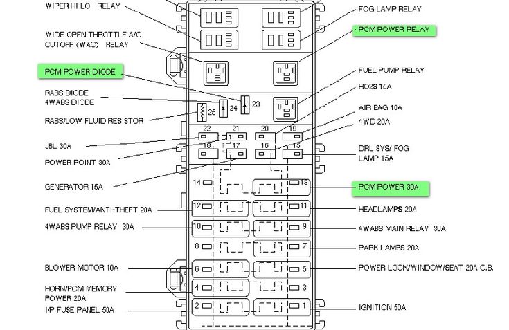
- Power Distribution Box (Engine Compartment): Situated under the hood, often near the battery. This box contains larger fuses and relays that protect high-current circuits, such as the starter motor, alternator, fuel pump, and ABS system. Some diagrams will also refer to this as a relay box due to the higher concentration of relays controlling the higher power systems.
Inside each box, you'll find:
- Fuses: These are sacrificial devices designed to protect circuits from overcurrent. They contain a thin wire that melts and breaks the circuit when excessive current flows through it. Fuses are rated in amperes (amps), indicating the maximum current they can handle before blowing.
- Relays: Electrically operated switches that control high-current circuits using a low-current control signal. They allow you to control powerful components (like the starter motor) with a small switch.
- Circuit Breakers: Similar to fuses, but resettable. They trip (open the circuit) when overloaded and can be reset manually or automatically after the overload is removed. The 1999 Explorer uses primarily fuses over breakers.
- The Fuse Box Housing: The plastic enclosure that holds the fuses and relays, often with a cover that indicates the location and function of each fuse.
Decoding the Symbols on the Diagram
The fuse box diagram uses symbols and conventions to represent different components and their connections. Here's a breakdown:
- Lines: Represent electrical wires or conductors. Solid lines indicate a direct connection, while dashed lines may indicate a ground connection or a control signal.
- Colors: Used to identify wires and circuits. While the diagram itself might be black and white, referencing a wiring diagram alongside it will show colored wires and allow for tracing the correct circuit. Common colors include red (power), black (ground), and various other colors for specific circuits.
- Fuse Symbols: Fuses are typically represented by a zig-zag line inside a rectangle or a small rectangle with a number inside. The number indicates the fuse's amperage rating.
- Relay Symbols: Relays are usually depicted as a coil symbol connected to a switch symbol.
- Component Icons: Icons representing specific components (headlights, radio, etc.) may be used to visually indicate the circuit's function. Look for a legend on the diagram to decode these.
- Numbers: Numbers next to fuses or relays usually correspond to the fuse/relay number within the fuse box. This is crucial for locating the correct component.
- Abbreviations: The diagram uses abbreviations like "IGN" (ignition), "ACC" (accessory), "PWR" (power), "GND" (ground), and "BATT" (battery).
How the Fuse Box Works: A Simplified Explanation
Imagine the electrical system as a network of pathways. The battery is the power source, and the wiring is the road. Fuses are like checkpoints. If too much traffic (current) tries to flow down a particular road (circuit), the checkpoint (fuse) closes down (blows) to prevent damage to the road (wiring and components). Relays are like traffic controllers, directing the flow of traffic based on signals from the driver (switches).
When you turn on the ignition, the electrical system activates. Current flows from the battery, through the fuses and relays, to the various components. Each fuse protects a specific circuit from overcurrent. If a short circuit occurs (e.g., a wire touches ground), the current surges, and the fuse blows, interrupting the flow of electricity and preventing damage.
Real-World Use: Basic Troubleshooting Tips
Let's say your radio suddenly stops working:
- Consult the Fuse Box Diagram: Locate the diagram for the interior fuse box.
- Identify the Radio Fuse: Find the fuse labeled "Radio" or "Audio" on the diagram. Note its location (fuse number) and amperage rating.
- Inspect the Fuse: Locate the corresponding fuse in the fuse box. Visually inspect it. If the thin wire inside the fuse is broken or blackened, the fuse is blown.
- Replace the Fuse: Replace the blown fuse with a new fuse of the same amperage rating. Never use a fuse with a higher amperage rating, as this could overload the circuit and cause a fire.
- Test the Radio: Turn on the ignition and check if the radio now works. If it does, the problem was a blown fuse.
- If the Fuse Blows Again: If the new fuse immediately blows, there's likely a short circuit in the radio wiring or the radio itself. Further investigation is required. You may need to consult a wiring diagram and use a multimeter to trace the fault.
Safety First: Handling Risky Components
Working with electrical systems can be dangerous. Here are some safety precautions:
- Disconnect the Battery: Before working on any electrical components, disconnect the negative terminal of the battery to prevent accidental shorts.
- Use Insulated Tools: Use tools with insulated handles to protect yourself from electric shock.
- Never Bypass a Fuse: Bypassing a fuse with a wire or a higher amperage fuse can overload the circuit and cause a fire.
- Be Careful Around High-Voltage Components: Components like the ignition coil and starter solenoid can carry high voltage even with the battery disconnected. Avoid touching these components while the ignition is on.
- Consult a Professional: If you're uncomfortable working with electrical systems or unsure about a particular procedure, consult a qualified mechanic.
The Power Distribution Box contains larger fuses and relays that handle high-current circuits (like the starter motor, alternator, and fuel pump). These circuits are more powerful and potentially more dangerous. Exercise extra caution when working in this area.
Remember, working with your car's electrical system can be very rewarding, but also quite dangerous. Taking your time and following proper procedures will ensure a safe and satisfying repair.
We have the 1999 Ford Explorer fuse box diagram available for download. This will give you a detailed visual reference to keep on hand while you're working on your Explorer. Feel free to download it and keep it handy for your next project or repair.