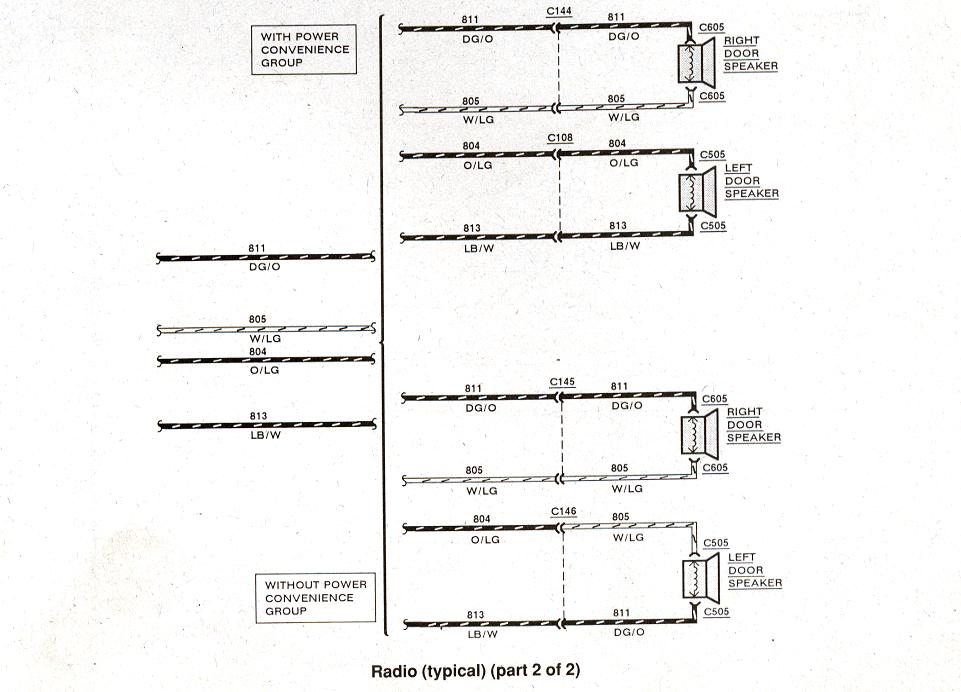
99 Ford Ranger Stereo Wiring Diagram
Working on your 1999 Ford Ranger's stereo system can be a rewarding DIY project, whether you're upgrading to a new head unit, replacing speakers, or troubleshooting wiring issues. A clear understanding of the 99 Ford Ranger stereo wiring diagram is absolutely essential for a successful and safe outcome. This article will break down that diagram, explaining its purpose, components, symbols, and how to use it for repairs and modifications. We’ll equip you with the knowledge to tackle your Ranger's audio system with confidence.
Purpose of the Wiring Diagram
The 99 Ford Ranger stereo wiring diagram serves as a detailed visual representation of the electrical connections within the audio system. It's more than just a pretty picture; it's a roadmap for:
- Repairs: Pinpointing shorts, open circuits, and damaged wires. Trying to fix electrical issues without a diagram is like navigating a maze blindfolded.
- Upgrades: Connecting aftermarket head units, amplifiers, subwoofers, and speakers correctly. Ensuring proper impedance matching and avoiding damage to your electrical system.
- Troubleshooting: Systematically diagnosing problems like no sound, distortion, or intermittent operation. A diagram helps isolate the faulty component.
- Learning: Gaining a deeper understanding of how your car's audio system is wired and operates. It's a valuable educational tool for anyone interested in automotive electronics.
Key Specs and Main Parts
Before diving into the diagram itself, let's outline the key components typically found in a 1999 Ford Ranger stereo system. Keep in mind that configurations can vary depending on the trim level and factory options.
- Head Unit (Radio): The central control unit, providing the user interface, AM/FM tuner, and often a cassette player or CD player. This is where all the audio signals originate.
- Speakers: Usually four speakers (two in the front doors and two in the rear). Some models may have upgraded speaker systems with separate tweeters.
- Wiring Harness: The bundle of wires connecting the head unit to the vehicle's electrical system and speakers. This is what the wiring diagram depicts.
- Antenna: Receives radio signals.
- Power Source: The vehicle's battery, providing the necessary voltage to power the system.
- Ground: Provides a return path for the electrical current. A good ground is crucial for proper operation.
The 1999 Ford Ranger's wiring system operates on a 12-volt DC system. This is important to remember when working with aftermarket components, as they must be compatible with this voltage.
Understanding the Symbols
The wiring diagram uses a standardized set of symbols to represent different components and connections. Learning these symbols is key to interpreting the diagram correctly.
- Solid Lines: Represent wires. The thickness of the line generally doesn't indicate wire gauge (diameter) on these diagrams, but it's still important to use appropriately sized wire for the current it will carry.
- Dashed Lines: May represent shielded cables or connections that are not always present (e.g., optional features).
- Circles with Numbers: Represent connectors. The number indicates the pin number on the connector.
- Color Codes: Each wire is identified by a color code (e.g., RD for red, BLK for black, WH/GN for white with a green stripe). These codes are essential for identifying the correct wires.
- Ground Symbol: Usually a series of horizontal lines decreasing in length, or a stylized representation of a chassis ground. Indicates where the circuit is connected to the vehicle's body for grounding.
- Speaker Symbol: Resembles a loudspeaker, indicating the connection point for the speakers.
- Fuse Symbol: A zigzag line within a rectangle, representing a fuse. Fuses are crucial safety devices that protect the system from overcurrent.
Pay close attention to the color codes. They are crucial for identifying the correct wires, especially when working behind the dashboard where the wiring harness can be a dense tangle of wires. The diagram will show the color of the wire at the pin. If the wire changes color further down the harness, that is something you will need to visually identify.
How It Works: Following the Signal Path
The stereo system works by taking an audio signal from a source (radio tuner, CD player, or auxiliary input), amplifying it, and sending it to the speakers. Here’s a simplified explanation of the signal path:
- Power: The head unit receives power from the vehicle's battery through the ignition switch and a constant 12V source. The ignition switch allows the radio to turn on and off with the car. The constant power source allows the radio to save presets and settings.
- Audio Input: The head unit receives audio signals from the radio tuner, CD player, or auxiliary input.
- Amplification: The head unit amplifies the audio signal. Some systems have an external amplifier for increased power.
- Speaker Output: The amplified signal is sent to the speakers through the wiring harness. Each speaker has a positive (+) and negative (-) terminal.
- Ground: The circuit is completed by grounding the system to the vehicle's chassis.
The wiring diagram shows the connections between each of these components. By tracing the lines and following the color codes, you can understand how the audio signal flows through the system.
Real-World Use: Basic Troubleshooting
Here are some common issues you might encounter and how the wiring diagram can help:
- No Power to the Radio: Check the fuse for the radio (usually located in the fuse box). Use the diagram to identify the power wire (usually red or yellow) and test for voltage with a multimeter. If there's no voltage, the fuse is likely blown or there's a break in the wire.
- No Sound from One Speaker: Check the speaker wiring at the head unit and at the speaker itself. Use the diagram to identify the speaker wires and test for continuity (a complete electrical path) with a multimeter. If there's no continuity, the wire is likely broken.
- Distortion or Static: Check the speaker wires for shorts to ground. Use the diagram to identify the speaker wires and use a multimeter to check for continuity between the speaker wire and the vehicle's chassis.
- Radio Turns On But No Sound: The problem could be with the amplifier (if equipped) or the speaker wiring. Use the diagram to trace the signal path and check for any breaks or shorts.
Example: Let's say your front right speaker isn't working. Consult the wiring diagram to identify the color codes for the front right speaker wires (typically a pair of wires, each with a different color combination). Use a multimeter to check for continuity between the head unit connector and the speaker connector. If you find a break in one of the wires, you know where to focus your repair efforts.
Safety Precautions
Working with automotive electrical systems can be dangerous if proper precautions are not taken. Always disconnect the negative battery terminal before working on any electrical components. This will prevent accidental shorts and potential injury.
The wiring harness contains components that can deliver a shock. Fuses, relays, and capacitors can store an electrical charge, even after the battery is disconnected. Handle these components with care. When soldering, make sure you are in a well-ventilated area.
Finally, be extremely careful when working with the airbag system. Improper handling of airbag wiring can cause accidental deployment, which can result in serious injury.
By using the wiring diagram in conjunction with a multimeter and a methodical approach, you can confidently diagnose and repair your 1999 Ford Ranger's stereo system. Remember to always prioritize safety and take your time.
We have the full 1999 Ford Ranger Stereo Wiring Diagram available for download. This diagram contains a much higher level of detail than can be presented in this article and includes wiring details for all factory options. Download it and print it out to have it handy as you work on your project.