A Diagram Locating A Check Valve In Relation Eith
Alright, let's dive into the world of check valves and how to properly identify their location within a system – specifically using a diagram. Understanding this is crucial for a range of tasks, from diagnosing engine performance issues to confidently tackling aftermarket modifications. We're going to break down a typical diagram and explain how it relates to a check valve's function in a real-world automotive setting.
Purpose of Understanding Check Valve Diagrams
Why bother learning this? Simple: it empowers you to troubleshoot problems effectively and safely. Imagine your car is losing boost pressure, or your EVAP system is throwing codes. Knowing how to read a diagram that pinpoints the check valve allows you to quickly locate it, test it, and determine if it's the culprit. It's far more efficient than blindly replacing parts and hoping for the best. This knowledge is also invaluable if you're planning any modifications that involve vacuum lines, fuel systems, or any system relying on one-way flow. For example, understanding the check valve’s role in the PCV system is important to avoid potential over-pressure issues.
Key Specs and Main Parts Involved
Before we dissect the diagram, let’s refresh some basics:
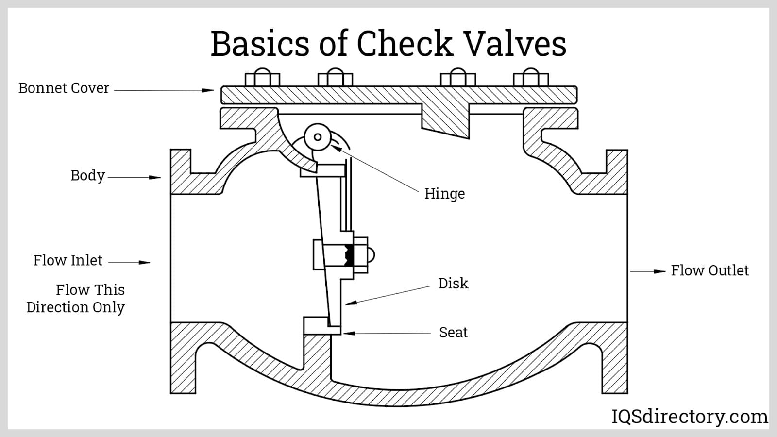
- Check Valve: A mechanical device that allows fluid (liquid or gas) to flow in only one direction. Inside, you'll typically find a poppet, ball, disc, or diaphragm that opens under forward pressure and closes under backpressure. Think of it like a one-way street for fluids.
- Vacuum Lines: Hoses that carry vacuum, which is negative pressure relative to atmospheric pressure. They are critical for various engine functions like brake boosters, HVAC controls, and fuel management.
- Fuel Lines: These lines transport fuel from the tank to the engine. They can be under significant pressure, especially in modern fuel-injected systems.
- PCV (Positive Crankcase Ventilation) System: A system designed to vent crankcase gases back into the intake manifold for combustion, reducing emissions and preventing pressure buildup in the crankcase. Check valves in the PCV system prevent boost pressure from entering the crankcase under boost.
Common specs to look for regarding check valves include:
- Cracking Pressure: The minimum pressure required for the valve to open.
- Material: The material of the valve body and internal components (e.g., plastic, metal, rubber), which must be compatible with the fluid it's handling (fuel, oil, air).
- Operating Temperature Range: The temperature range within which the valve will function reliably.
- Flow Rate: The amount of fluid that can pass through the valve per unit of time.
Understanding Diagram Symbols
This is where things get interesting. A typical automotive schematic diagram uses specific symbols to represent components. Here's a breakdown of what you might encounter regarding check valves:
- Check Valve Symbol: Typically, a check valve is represented by a triangle pointing towards a line. The triangle indicates the direction of permitted flow. There's often a small line or bar blocking the pointed end of the triangle, signifying the one-way nature of the valve. If a circle or square surrounding the check valve exists, it signifies this part is an assembly and has other parts connected to it.
- Lines:
- Solid Lines: Generally represent physical pipes or hoses carrying fluid or vacuum.
- Dashed Lines: Often indicate control lines or signal lines, perhaps electrical connections related to a system controlled by vacuum or fluid pressure.
- Thick Lines: Might indicate high-pressure lines, such as fuel lines.
- Colors: While not standardized across all manufacturers, colors often differentiate types of fluids or systems. For example:
- Blue: Water-based fluids (e.g., coolant, washer fluid).
- Red: Fuel or oil.
- Green: Vacuum lines.
- Component Labels: Each component, including the check valve, will typically have a label (e.g., CV-1, PCV Valve) that corresponds to a part number or description in the diagram's parts list.
Important: Always consult the legend or key accompanying the diagram! It's the Rosetta Stone for understanding the specific symbols and conventions used.
How It Works: Tracing the Flow
The beauty of a diagram lies in its ability to visually represent how a system functions. To understand how the check valve operates within the system, follow these steps:
- Locate the Check Valve Symbol: Find the triangle-and-line symbol we discussed.
- Identify the Direction of Flow: The triangle points in the direction of permitted flow. Note which components the valve is connected to on either side.
- Trace the Lines: Follow the lines connected to the check valve to see where the fluid or gas is coming from and where it's going.
- Understand the System's Purpose: Is the check valve part of the EVAP system, the PCV system, the fuel system, or something else? Knowing the overall function helps you understand the valve's specific role. For instance, within the EVAP system, a check valve prevents fuel vapors in the fuel tank from entering the engine when the engine is not running.
By carefully tracing the lines and understanding the system's purpose, you can deduce how the check valve prevents backflow and ensures proper operation. For example, if the diagram shows the check valve positioned between the intake manifold and a charcoal canister in the EVAP system, you can infer that it prevents vacuum from the manifold from drawing fuel vapors out of the canister when the system is not actively purging.
Real-World Use: Basic Troubleshooting Tips
Let's say you suspect a faulty check valve is causing a problem. Here are some basic troubleshooting steps, assuming you have located the check valve using the diagram:
- Visual Inspection: Check the valve and connecting hoses for cracks, leaks, or damage.
- Flow Test: Disconnect the valve (carefully!) and try blowing through it in both directions. It should only allow airflow in one direction. Use a vacuum tester to verify it holds vacuum in the correct direction.
- Component Testing (if applicable): If the check valve is part of a larger assembly with sensors or other components, test those components according to the service manual.
- Smoke Test: Using a smoke machine to pressurize a vacuum system can reveal leaks around a faulty check valve.
Remember to consult your vehicle's service manual for specific diagnostic procedures and torque specifications.
Safety Considerations
Working with automotive systems can be dangerous. Keep these points in mind:
- Fuel Systems: Fuel is highly flammable. Disconnect the battery and take precautions to prevent sparks or open flames when working on fuel lines or components. Depressurize the fuel system before disconnecting any lines.
- Vacuum Systems: While vacuum is generally not dangerous, some systems may contain harmful vapors. Work in a well-ventilated area.
- High-Pressure Systems: Systems like power steering or air conditioning can operate at very high pressures. Follow proper procedures for depressurizing these systems before working on them.
- Personal Protective Equipment (PPE): Wear safety glasses, gloves, and appropriate clothing to protect yourself from fluids, sharp edges, and other hazards.
Always disconnect the negative battery cable before working on any electrical or fuel system components. Pay close attention to the specific diagram of your car. A diagram’s format differs among car manufacturers and across different models.
Understanding diagrams of check valves can seem daunting, but with a little practice, you'll be able to trace the flow, diagnose problems, and confidently tackle repairs and modifications. This knowledge will save you time, money, and frustration in the long run.
We have a sample diagram file readily available for your reference. If you are interested, contact us and you can download the diagram that we discussed to further deepen your understanding.