
Ac Compressor Ac Relay Wiring Diagram
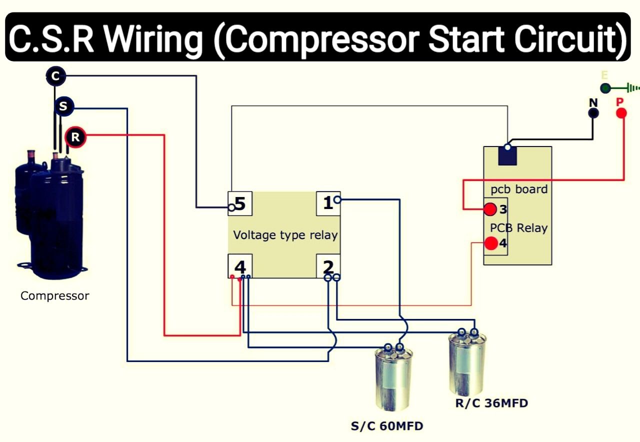
Understanding your car's AC compressor relay wiring diagram is essential for anyone looking to diagnose AC problems, perform maintenance, or even modify their vehicle. This isn't just about fixing a broken AC system; it's about grasping a fundamental aspect of automotive electrical systems. Whether you're replacing a faulty compressor, adding an aftermarket cooling fan, or just learning how your car works, this knowledge is invaluable.
Purpose of the AC Compressor Relay Wiring Diagram
The AC compressor relay wiring diagram serves as a roadmap for the electrical circuit that controls your AC compressor. It illustrates how different components are connected, the types of wires used, and the functions of each part. This diagram is vital for:
- Troubleshooting: Pinpointing the source of AC problems, such as a non-functional compressor or intermittent cooling.
- Repairing: Identifying damaged wires, faulty relays, or other electrical components that need replacement.
- Modifying: Safely integrating aftermarket components, like performance cooling fans or enhanced AC systems.
- Learning: Gaining a deeper understanding of automotive electrical systems and how they work.
Key Specs and Main Parts
The AC compressor circuit typically involves several key components, each with specific characteristics:
- Battery: The power source for the entire system, usually 12V DC. The battery provides the electrical energy needed to power the AC compressor.
- Fuse: A safety device that protects the circuit from overcurrent. If the current exceeds the fuse's rating, the fuse blows, interrupting the circuit and preventing damage to components.
- AC Compressor Relay: An electrically operated switch that controls the flow of power to the AC compressor. It allows a low-current signal from the car's computer (ECU) or AC switch to control a high-current circuit that powers the compressor.
- AC Compressor Clutch: An electromagnetic clutch that engages or disengages the AC compressor from the engine's crankshaft. When engaged, the compressor pumps refrigerant, cooling the air. When disengaged, the compressor is idle.
- Pressure Switch(es): Sensors that monitor the refrigerant pressure in the system. They prevent the compressor from running if the pressure is too low (indicating a leak) or too high (indicating a blockage). Common types include low-pressure switches and high-pressure cut-off switches.
- Thermostat/Temperature Sensor: Detects the evaporator core temperature. If the core gets too cold (near freezing), the sensor signals the system to disengage the compressor, preventing ice buildup.
- Engine Control Unit (ECU): In modern vehicles, the ECU often controls the AC compressor based on various inputs, including engine load, throttle position, and ambient temperature.
- Wiring Harness: Bundles of wires that connect all the components together. They are typically color-coded for easy identification.
Understanding the Symbols
Wiring diagrams use standardized symbols to represent components and connections. Here's a breakdown of common symbols:
- Solid Lines: Represent wires connecting different components. The thickness of the line may sometimes (but not always) indicate the wire gauge.
- Dashed Lines: Often indicate grounding connections. A dashed line might also represent a signal wire carrying data between components.
- Circles: Represent various components, such as sensors, switches, or fuses. Specific shapes within the circle differentiate the component type.
- Rectangles: Commonly used to represent relays, ECUs, or other electronic modules.
- Ground Symbol: A symbol that looks like an inverted triangle or a series of horizontal lines decreasing in length, indicating a connection to the vehicle's chassis ground.
- Color Codes: Wires are color-coded to help identify their function. Common colors include red (power), black (ground), blue (signal), etc. The diagram's legend will provide a key to these color codes.
It's crucial to refer to the legend accompanying the specific diagram you're using, as symbol conventions can vary slightly between manufacturers.
How It Works
The AC compressor circuit is a relatively simple but vital system. Here's a simplified explanation of how it typically operates:
- The driver activates the AC system, usually by pressing the AC button on the dashboard.
- This signal is sent to the ECU or directly to the AC compressor relay.
- The ECU (or the AC switch) checks various inputs, such as engine temperature, refrigerant pressure, and ambient temperature, to determine if it's safe to engage the compressor.
- If all conditions are met, the ECU (or AC switch) sends a low-current signal to the AC compressor relay.
- The relay, acting as an electrically controlled switch, closes its contacts, allowing high-current power from the battery to flow to the AC compressor clutch.
- The energized clutch engages, mechanically linking the compressor to the engine's crankshaft.
- The compressor starts pumping refrigerant, initiating the cooling cycle.
- Pressure switches monitor refrigerant pressure, and the thermostat monitors evaporator core temperature. If either detects an abnormal condition, it can signal the ECU to disengage the compressor, protecting the system.
Real-World Use: Basic Troubleshooting Tips
Here are some common AC problems and how the wiring diagram can help you diagnose them:
- AC Compressor Not Engaging: Use a multimeter to check for voltage at the AC compressor clutch connector when the AC is turned on. If there's no voltage, trace the circuit back through the relay, fuse, and switches to identify the fault. Start by checking the fuse.
- AC Compressor Running Constantly: This could be a faulty relay (contacts stuck closed), a malfunctioning pressure switch, or an ECU problem. The diagram helps you isolate which component is responsible.
- Intermittent AC Operation: Could be caused by a loose connection, a corroded wire, or a failing relay. Use the diagram to visually inspect the wiring harness and connectors for damage. Pay special attention to ground connections.
When troubleshooting, always use a multimeter to check for voltage, continuity, and resistance. Refer to the diagram to identify the correct test points and expected values.
Safety Considerations
Working with automotive electrical systems can be dangerous. Always observe the following safety precautions:
- Disconnect the Battery: Before working on any electrical component, disconnect the negative battery terminal to prevent short circuits and electrical shocks.
- Use Proper Tools: Use insulated tools to prevent accidental shorts.
- Identify High-Voltage Components: The AC compressor clutch circuit typically involves relatively low voltages (12V DC), but be aware of other high-voltage systems in the vehicle, such as the ignition system.
- Consult the Wiring Diagram: Always refer to the wiring diagram to ensure you are working on the correct circuit and understand the function of each component.
- If unsure, consult a professional mechanic. Electrical systems can be complex, and improper repairs can damage your vehicle or cause personal injury.
Important Note: The AC system contains pressurized refrigerant, which can be harmful if released into the atmosphere. If you suspect a refrigerant leak, consult a qualified AC technician to recover and recharge the system. Do not attempt to handle refrigerant yourself without proper training and equipment.
Locating and Using Your Specific Diagram
It's absolutely vital to use the wiring diagram specifically made for your car's year, make, and model. Generic diagrams can be misleading. You can usually find these diagrams in:
- Your car's repair manual (Haynes, Chilton, etc.)
- Online databases (often subscription-based)
- Sometimes, printed on a sticker under the hood or in the glove box.
We have a general AC compressor relay wiring diagram file available for download. However, always double-check it against your vehicle's specific documentation.
This document provides a solid foundation for understanding your AC compressor circuit, enabling you to confidently diagnose and repair problems, and perform modifications. Happy wrenching!