A/c Compressor Wiring Harness Plug For Honda Civic
Alright folks, let's dive into the often-overlooked but crucial wiring harness plug for the A/C compressor in your Honda Civic. This guide is geared toward the experienced DIYer, the modder looking to understand their car inside and out, and anyone who wants to be more confident tackling their own A/C system repairs. Forget cryptic service manuals; we're breaking it down in plain English. We have the full wiring diagram available for download too – more on that later.
Purpose: Why Bother Understanding This?
Why should you care about the A/C compressor wiring harness plug? Several reasons:
- Troubleshooting A/C Issues: A malfunctioning A/C system can stem from a faulty wiring connection just as easily as a bad compressor. Understanding the plug lets you pinpoint the problem with a multimeter instead of guessing.
- Performing A/C System Repairs: Replacing the compressor, pressure switch, or other A/C components often requires disconnecting and reconnecting this harness. Proper identification and handling prevent damage and ensure a correct re-assembly.
- Electrical Modifications: For those modding or adding aftermarket components, knowledge of the A/C circuit and how it interacts with the ECU is invaluable for safe and effective integration.
- General Automotive Knowledge: Even if your A/C is working perfectly, understanding how this plug functions is a great step towards mastering automotive electrical systems.
Key Specs and Main Parts
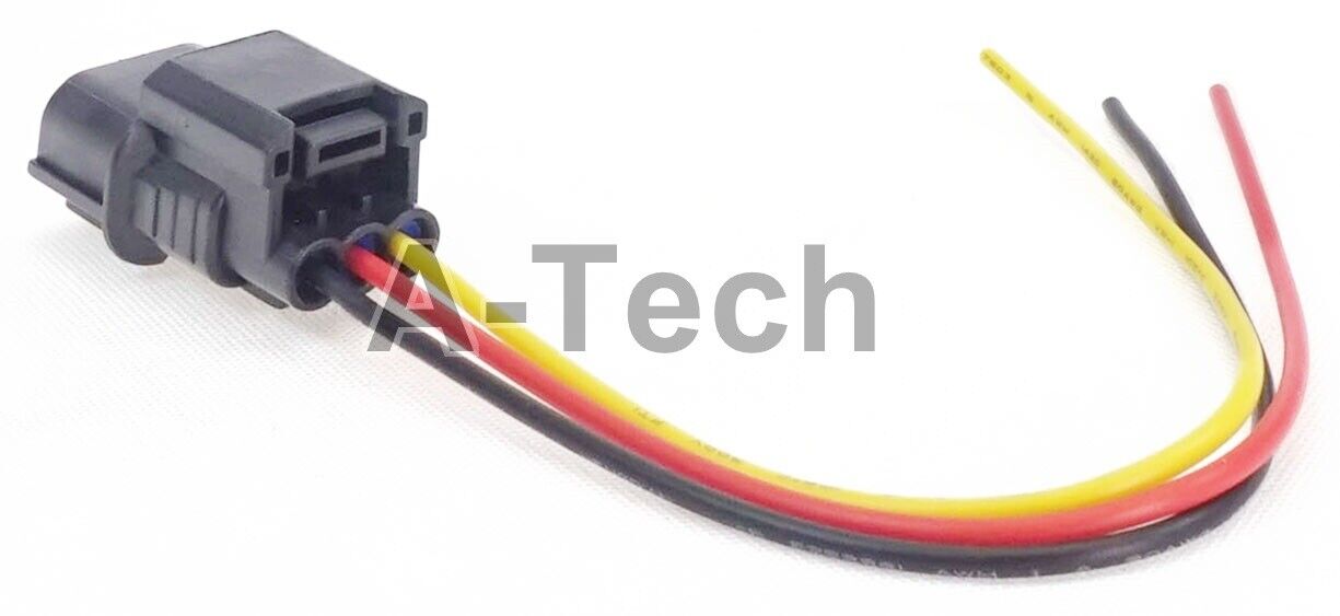
The A/C compressor wiring harness plug is typically a small, multi-pin connector located directly on the compressor itself. The specific number of pins can vary slightly depending on the Civic generation and trim level, but generally, you'll find connectors with 2, 3, or 4 pins. Each pin carries a specific signal crucial for the A/C system's operation.
Here's a breakdown of the typical components and their roles:
- Compressor Clutch Relay Signal: This is the most important wire. It provides the 12V+ power needed to engage the compressor clutch, which is the electromagnetic mechanism that physically connects the compressor to the engine's accessory belt. When energized, the clutch engages, and the compressor starts pumping refrigerant.
- Ground: Provides the necessary ground connection for the compressor clutch circuit to function.
- Pressure Switch Signal (High/Low): Some models incorporate a pressure switch signal that monitors the refrigerant pressure within the system. This signal informs the ECU if the pressure is too high (potentially damaging) or too low (indicating a leak or insufficient refrigerant). The ECU will then disengage the compressor clutch to prevent damage. This signal can be either digital (on/off) or analog (variable voltage).
- Compressor Speed Sensor (rare): Some advanced systems use a speed sensor integrated into the compressor to provide feedback to the ECU about the compressor's rotational speed. This helps the ECU optimize engine performance and prevent compressor damage.
Symbols and Diagram Interpretation
Understanding the wiring diagram is key. Here's how to interpret the symbols and conventions you'll typically encounter:
- Solid Lines: Represent wires. The thicker the line, the heavier gauge (thicker) the wire is, indicating its current-carrying capacity.
- Dashed Lines: Often represent wires within a multi-wire harness.
- Colors: Wires are almost always color-coded (e.g., Blue/White stripe, Green, Black). Refer to the legend on the diagram to understand the specific function of each color. Pay close attention to stripe colors.
- Ground Symbol: Looks like an upside-down Christmas tree or a series of stacked horizontal lines. It indicates a connection to the vehicle's chassis ground.
- Connector Symbols: Represent the physical connectors. Usually, a square or rectangular shape with numbers indicating pin positions.
- Relay Symbols: Depict the A/C compressor clutch relay. This relay acts as a switch, allowing a small current from the ECU to control a larger current to the compressor clutch.
- Fuse Symbols: Indicate the fuse protecting the A/C compressor circuit. Knowing the fuse location is vital for troubleshooting.
- Pressure Switch Symbols: Shows the pressure switch that protects the A/C system.
Example: A wire labeled "BLU/WHT" likely indicates a blue wire with a white stripe. Trace this wire on the diagram to see where it connects. Often, this color will be associated to +12V power feed. This will allow for quick identification of a suspect wire.
How It Works: A Simplified Explanation
The A/C compressor wiring harness plug is the interface between the car's electrical system and the A/C compressor. Here's a simplified explanation of how it all works:
- The Driver Activates the A/C: When you press the A/C button on your dashboard, the request is sent to the ECU (Engine Control Unit).
- ECU Check Conditions: The ECU checks several conditions, such as engine temperature, refrigerant pressure (via the pressure switch), and engine load. If all conditions are met, the ECU proceeds to engage the A/C compressor.
- ECU Signals the Relay: The ECU sends a low-current signal to the A/C compressor clutch relay.
- Relay Closes the Circuit: The relay acts like a switch, closing the circuit that provides high-current power to the A/C compressor clutch.
- Clutch Engages: With power applied, the compressor clutch engages, physically connecting the compressor to the engine's accessory belt. The compressor starts pumping refrigerant.
- Feedback (if applicable): If the system has a compressor speed sensor, it sends feedback to the ECU about the compressor's speed, allowing the ECU to optimize engine performance.
The wiring harness plug facilitates this entire process by providing the necessary connections for power, ground, and control signals.
Real-World Use: Basic Troubleshooting
Let's say your A/C isn't working. Here's how understanding the wiring harness plug can help you troubleshoot:
- Visual Inspection: Start with a visual inspection of the plug. Look for corrosion, damaged wires, or loose connections. Clean the plug with electrical contact cleaner and ensure it's securely connected.
- Check the Fuse: Consult your owner's manual for the A/C compressor fuse location. Test the fuse with a multimeter. If it's blown, replace it. However, a frequently blown fuse indicates a more serious problem.
- Test for Voltage: Using a multimeter, check for voltage at the compressor clutch relay signal wire (with the A/C turned on and the engine running). You should see approximately 12V. If not, the problem lies upstream (relay, ECU, wiring).
- Check Ground: Verify that the ground wire has a good connection to the chassis ground. Use a multimeter to check for continuity between the ground wire and a known good ground point.
- Bypass the Relay (Advanced): Use caution! Carefully bypass the A/C compressor clutch relay by manually applying 12V directly to the compressor clutch terminal on the harness plug. If the compressor engages, the problem is likely with the relay or its control circuit. Never attempt this if you are not comfortable working with electrical circuits.
Safety First! Highlighting Risky Components
Working with automotive electrical systems can be dangerous. Always disconnect the negative battery terminal before working on any electrical components. The A/C compressor clutch relay circuit carries significant current, so be careful when testing and probing wires. The refrigerant lines contain pressurized refrigerant, which can cause frostbite if released improperly. If you suspect a refrigerant leak, consult a qualified A/C technician.
The A/C compressor itself can be hot to the touch after the engine has been running. Allow it to cool down before working near it. Never puncture or damage the refrigerant lines.
Get the Diagram!
Understanding the specific wiring diagram for your Honda Civic's year and trim level is crucial. We have a comprehensive diagram available for download. This diagram shows wire colors, connector locations, and circuit layouts specific to your vehicle. With the detailed diagram, combined with the information in this article, you'll be well-equipped to diagnose and repair your A/C system with confidence.
Remember to always consult your vehicle's repair manual and follow proper safety procedures when working on your car. Good luck!