Accelerator Pedal Position Sensor Diagram
Alright, let's dive into the Accelerator Pedal Position (APP) sensor diagram. If you're tinkering with your engine performance, diagnosing throttle issues, or just want a deeper understanding of your car's electronics, knowing how to read and interpret this diagram is crucial. We're going to break it down in a way that even an experienced DIYer can grasp, but remember, always consult your specific vehicle's service manual for the most accurate information.
Purpose of the APP Sensor Diagram
The APP sensor diagram, also sometimes referred to as the throttle position sensor (TPS) diagram, is your roadmap to understanding how your accelerator pedal communicates with the engine control unit (ECU). It shows you the wiring layout, the internal workings of the sensor, and how it connects to other parts of the system. Understanding this allows you to:
- Diagnose Problems: Identify faulty wiring, sensor issues, or ECU communication problems that cause poor acceleration, stalling, or error codes.
- Perform Repairs: Replace a damaged sensor or repair broken wiring with confidence.
- Understand Modifications: Modify or upgrade your throttle system for better performance (with proper knowledge and precautions, of course).
- Deepen Your Knowledge: Become a more competent car owner and mechanic.
Key Specs and Main Parts
Before we jump into the diagram itself, let's define the key components we'll see represented:
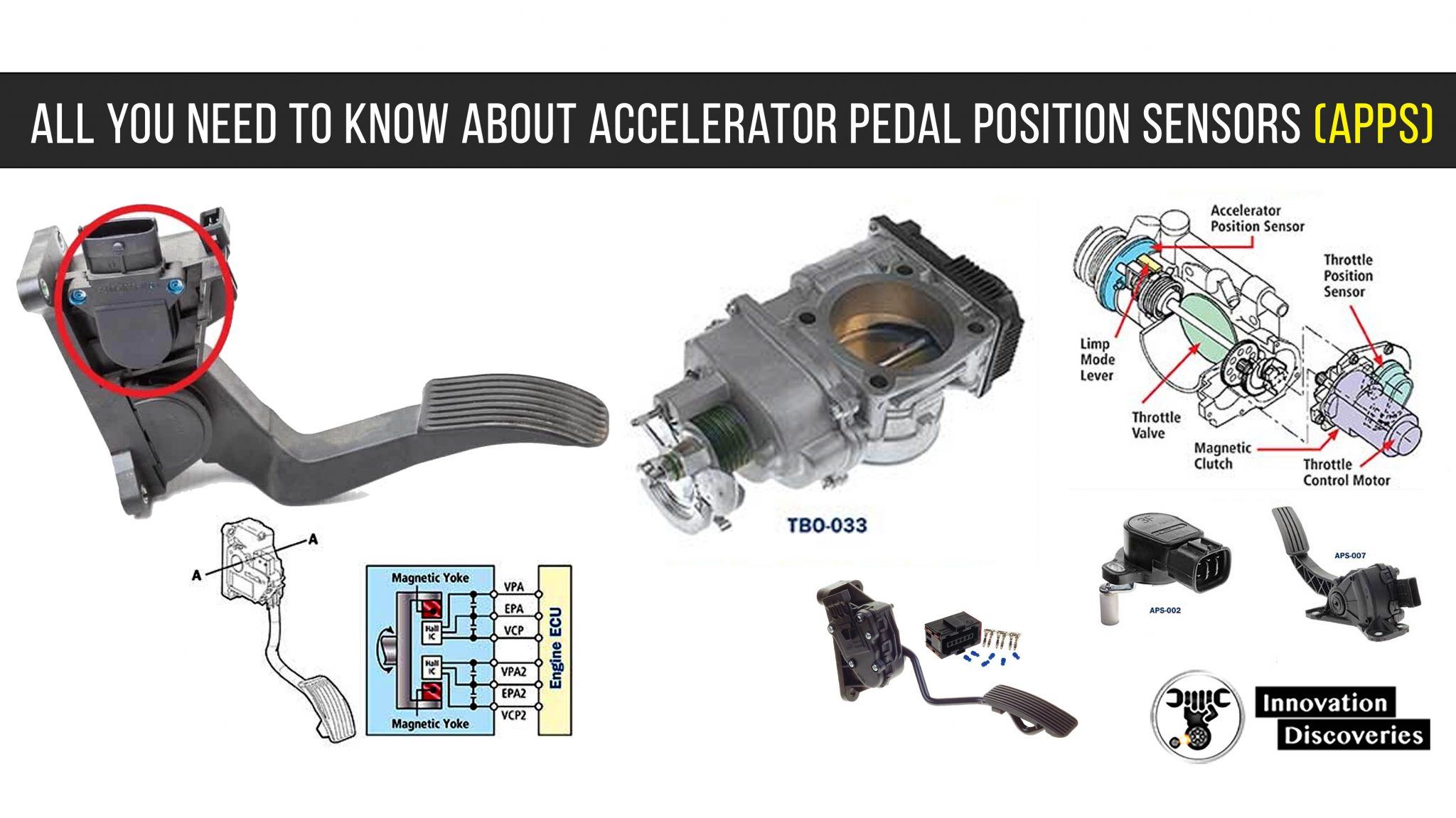
- Accelerator Pedal Position (APP) Sensor: The main component. It's a potentiometer (a variable resistor) that changes its resistance value based on the position of the accelerator pedal. Some vehicles use two APP sensors for redundancy and enhanced safety; these are often referred to as APP1 and APP2.
- Engine Control Unit (ECU): The car's brain. It reads the signal from the APP sensor and uses it to determine how much fuel to inject and when to ignite the spark plugs.
- Wiring Harness: The network of wires that connect the APP sensor to the ECU, ground, and power source.
- Connectors: The physical plugs that connect the APP sensor and wiring harness. These can sometimes be a source of corrosion or loose connections, causing issues.
- Voltage Supply: Typically a 5-volt reference voltage provided by the ECU to power the APP sensor.
- Ground: Provides a return path for the electrical current.
A typical APP sensor diagram will show the following:
- Sensor Type: Indicates if the sensor is a potentiometer, Hall-effect sensor, or another type.
- Voltage Range: The expected voltage output range of the sensor, typically between 0 and 5 volts.
- Pinout: The specific function of each pin on the APP sensor connector (e.g., 5V reference, signal, ground).
- Resistance Values: If it’s a potentiometer, it may show resistance values at different pedal positions.
Symbols: Decoding the Diagram
Understanding the symbols on the diagram is essential. Here's a breakdown of common elements:
- Solid Lines: Represent wires. Thicker lines might indicate a larger gauge wire.
- Dashed Lines: Sometimes represent shielding or ground connections.
- Colors: Wires are often color-coded (e.g., red for power, black for ground). The diagram will have a key or legend explaining the color codes. Always double-check the wiring diagram specific to your car, as color codes can vary between manufacturers and even model years.
- Ground Symbol: Usually looks like a series of downward-pointing lines connected to each other.
- Resistor Symbol: A jagged line represents a resistor.
- Potentiometer Symbol: A resistor symbol with an arrow pointing to it, indicating a variable resistance.
- Connector Symbol: Often represented by a square or rectangular box with numbers or letters indicating the pin numbers.
- ECU Symbol: A box labeled "ECU" or "PCM" (Powertrain Control Module), indicating the connection point to the computer.
- Voltage Source: A symbol indicating a DC voltage source, often labeled with the voltage value (e.g., 5V).
Also pay attention to wire gauge, which isn't always explicitly stated but can be inferred from the line thickness in some diagrams. Using the wrong gauge wire during repairs can lead to overheating and electrical fires.
How It Works
The APP sensor's operation is relatively simple:
- The ECU sends a 5-volt reference voltage to the APP sensor.
- As you press the accelerator pedal, the sensor's internal potentiometer changes its resistance.
- This change in resistance alters the voltage signal that the sensor sends back to the ECU.
- The ECU interprets this voltage signal as the desired throttle position.
- Based on the throttle position, the ECU adjusts the fuel injection, ignition timing, and other parameters to control engine power.
In systems with two APP sensors (APP1 and APP2), the ECU compares the signals from both sensors to ensure accuracy and detect potential failures. The two sensors are typically designed to have inverse outputs – for example, as APP1 voltage increases, APP2 voltage decreases.
Real-World Use: Basic Troubleshooting
Here's how you can use the APP sensor diagram for basic troubleshooting:
- Check for Error Codes: Use an OBD-II scanner to retrieve diagnostic trouble codes (DTCs). Codes related to the APP sensor (e.g., P0120, P0121, P0122, P0123) can indicate a problem.
- Inspect Wiring: Visually inspect the wiring harness and connectors for damage, corrosion, or loose connections. Refer to the diagram to identify the specific wires and connectors related to the APP sensor.
- Test Voltage: Use a multimeter to measure the voltage at the APP sensor connector. Check for the 5-volt reference voltage, ground, and signal voltage. Compare the signal voltage at different pedal positions to the expected values outlined in the service manual.
- Test Resistance: With the ignition off and the connector disconnected, use a multimeter to measure the resistance across the sensor terminals. Compare the resistance values at different pedal positions to the specifications in the service manual.
- Continuity Test: Use a multimeter to check the continuity of the wires between the APP sensor and the ECU. This ensures that there are no breaks or shorts in the wiring.
Example Scenario: You get a P0121 code (Throttle/Pedal Position Sensor/Switch A Circuit Range/Performance Problem). You consult the wiring diagram and find the APP sensor pinout. You use a multimeter to check for 5V reference, ground, and a signal voltage that changes smoothly as you press the pedal. If the voltage is erratic or missing, you might have a bad sensor or a wiring issue. If the wiring is good, the sensor is likely faulty and needs replacement.
Safety First!
Working with automotive electrical systems can be dangerous. Here are some safety precautions:
- Disconnect the Battery: Always disconnect the negative battery terminal before working on any electrical components. This prevents accidental shorts and electrical shocks.
- Use Proper Tools: Use insulated tools designed for automotive electrical work.
- Avoid Working in Wet Conditions: Water can conduct electricity and increase the risk of electric shock.
- Be Careful with Wiring: Avoid damaging or cutting wires. If you need to cut a wire, use proper wire strippers and connectors to ensure a secure and reliable connection.
- Understand Your Limits: If you're not comfortable working on electrical systems, consult a qualified mechanic.
The ECU itself is a highly sensitive electronic component. Never apply excessive voltage or current to the ECU connectors. Improper handling can damage the ECU and require costly repairs or replacement. Static electricity can also damage the ECU; use an anti-static wrist strap when handling it.
Remember, this is a general overview. Your specific vehicle's APP sensor and wiring configuration may differ. Always consult your vehicle's service manual for the most accurate and detailed information. We have a generic file available for download to help illustrate these points further. However, remember that it is generic and should only be used for informational purposes; always refer to your car's specific diagram for actual repairs.