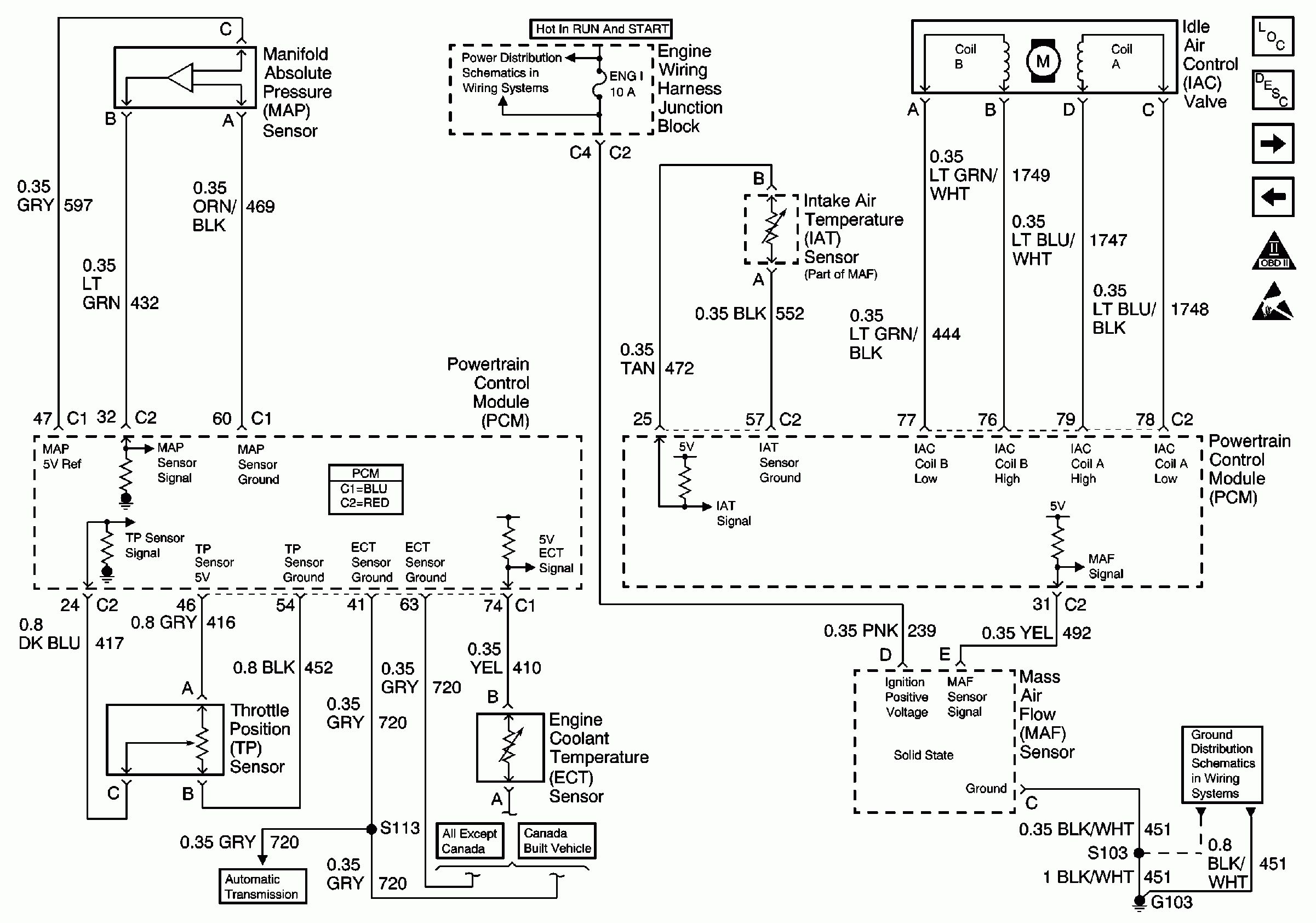
Accelerator Pedal Position Sensor Wiring Diagram
Okay, so you're diving into the world of Accelerator Pedal Position (APP) sensors. Smart move! Understanding the APP sensor wiring diagram is crucial for accurate diagnostics, repairs, performance tuning, and even custom modifications. This isn't just about knowing which wire goes where; it's about understanding the entire system that translates your foot pressure into engine response. Think of it as the electronic bridge between your intentions and your engine's actions. We're going to break down the wiring diagram in a way that even someone relatively new to automotive electronics can grasp. Plus, we've got a downloadable diagram available – more on that later.
Why Bother with an APP Sensor Wiring Diagram?
Let's be honest, nobody *wants* to stare at wiring diagrams unless they absolutely have to. But here's why it's worth your time:
- Troubleshooting: Engine hesitations, limp mode, or a check engine light related to throttle issues almost always involve the APP sensor. The diagram allows you to pinpoint the source of the problem, whether it's a broken wire, a short circuit, or a faulty sensor itself.
- Repairing: Damaged wiring harnesses happen. Rodents, heat, and general wear and tear can all take their toll. The diagram is your roadmap for repairing or replacing sections of the harness correctly, ensuring proper connections and preventing further damage.
- Performance Tuning: If you're planning to remap your ECU (Engine Control Unit) or install a throttle controller, you *need* to understand how the APP sensor interacts with the engine management system. Incorrect wiring can lead to unpredictable and potentially dangerous results.
- Learning: More generally, understanding the APP sensor helps you understand how modern drive-by-wire systems operate, and deepens your overall automotive knowledge.
Key Specs and Main Parts of the APP Sensor Circuit
Before we jump into the diagram itself, let’s familiarize ourselves with the key components:
- APP Sensor(s): Most vehicles use *two* APP sensors. This redundancy is a safety feature. If one sensor fails, the other provides a backup signal, preventing uncontrolled acceleration. The ECU constantly compares the signals from both sensors. A significant discrepancy triggers a fault code and can activate limp mode.
- ECU (Engine Control Unit): The brain of the operation. It receives the APP sensor signals, interprets them, and adjusts the throttle plate accordingly.
- Wiring Harness: The network of wires connecting the APP sensor(s) to the ECU and, in some cases, to the vehicle's ground.
- Connectors: These ensure secure and reliable connections between the sensor, harness, and ECU. Corrosion and loose connections are common causes of APP sensor issues.
Typical APP sensors are potentiometer-based. A potentiometer is a variable resistor. As the accelerator pedal is pressed, the potentiometer changes its resistance, which affects the voltage signal sent to the ECU.
Decoding the Wiring Diagram: Lines, Colors, and Symbols
Okay, let’s dive into the diagram itself. Here's what you'll usually find:
Lines: The Pathways of Electricity
- Solid Lines: Represent wires. The thicker the line, generally, the more substantial the wire (though this isn't always strictly adhered to).
- Dashed Lines: May indicate shielded wires (used to protect the signal from electromagnetic interference) or wires that are part of a larger harness bundle.
Colors: A Universal Language (Mostly)
Wire colors are *supposed* to be standardized, but variations exist between manufacturers. However, some common conventions apply:
- Red: Typically indicates a power supply (e.g., +5V reference voltage).
- Black: Usually represents ground (0V).
- Other Colors (e.g., Green, Blue, Yellow, White): Used for signal wires. These colors are less standardized and vary more between manufacturers.
Important: Never assume a wire's function based solely on its color. Always verify with the wiring diagram for your specific vehicle.
Symbols: Representing Components
- Rectangles: Often used to represent connectors or the ECU.
- Circles with a line through them: Usually indicate a ground connection.
- Resistors (zig-zag lines): May be shown within the APP sensor itself, representing the potentiometer.
- Potentiometer symbol (resistor with an arrow): Represents the variable resistance within the APP sensor.
The diagram will also include labels indicating the pin numbers on the connectors, the wire gauge (thickness), and the function of each wire (e.g., "APP Sensor 1 Signal," "+5V Reference," "Ground").
How the APP Sensor System Works
Here’s the simplified breakdown of how the APP sensor system functions:
- Driver Input: You press the accelerator pedal.
- Sensor Activation: The movement of the pedal changes the resistance of the potentiometers inside the APP sensor(s).
- Signal Generation: The change in resistance results in a change in voltage signals sent to the ECU. Typically, one sensor’s voltage increases with pedal travel, while the other’s decreases (though there are variations).
- ECU Interpretation: The ECU reads these voltage signals and compares them. Based on the values and their relationship to each other, the ECU determines the driver's desired throttle position.
- Throttle Plate Control: The ECU sends a signal to the throttle actuator (a motor) to open or close the throttle plate in the intake manifold.
- Engine Response: The amount of air entering the engine is controlled, which in turn controls the engine's power output.
Real-World Use: Basic Troubleshooting Tips
So, the check engine light is on, and you suspect the APP sensor. Here's how you can use the wiring diagram to start troubleshooting:
- Get the Code: Use an OBD-II scanner to retrieve the Diagnostic Trouble Code (DTC). This code will provide valuable information about which part of the APP sensor system is malfunctioning (e.g., "P2122 - APP Sensor 1 Circuit Low Input").
- Consult the Diagram: Locate the APP sensor wiring diagram for your specific vehicle (year, make, and model are crucial).
- Check the Connections: Visually inspect the APP sensor connector and the ECU connector for any signs of corrosion, damage, or loose connections. Clean the connectors with electrical contact cleaner if necessary.
- Test the Voltage: Use a multimeter to measure the voltage at the APP sensor connector. Check for the presence of the +5V reference voltage and ground. If either is missing, trace the wiring back to the ECU to identify the break.
- Check Signal Wires: With the key on and the engine off, slowly press and release the accelerator pedal while monitoring the voltage on the signal wires. The voltage should change smoothly and predictably. Erratic or no voltage change indicates a faulty sensor or wiring problem.
- Continuity Test: With the power off and the connectors disconnected, use a multimeter to check the continuity of the signal wires between the APP sensor connector and the ECU connector. A lack of continuity indicates a broken wire.
Safety First: Highlighting Risky Components
Working with automotive electronics requires caution:
- Battery Disconnect: Always disconnect the negative battery terminal before working on any electrical components. This prevents accidental short circuits and potential damage to the ECU.
- Airbag Systems: Be extremely careful when working near airbag systems. Accidental deployment can cause serious injury. Consult your vehicle's service manual for proper procedures.
- Fuel System: Avoid creating sparks near the fuel system. Fuel vapors are highly flammable.
- ECU Sensitivity: The ECU is a delicate electronic device. Avoid static electricity and handle it with care.
Warning: Incorrect wiring can damage the ECU and other sensitive components. If you're unsure about any step, consult a qualified mechanic.
By understanding the APP sensor wiring diagram, you empower yourself to diagnose and repair issues related to your vehicle's electronic throttle control system. This knowledge not only saves you money on repairs but also gives you a deeper understanding of how your car works.
Ready to dive deeper? As mentioned earlier, we have a sample APP sensor wiring diagram file available for download. This diagram provides a visual representation of a typical setup and can serve as a reference point for understanding the principles we've discussed. (Note: this diagram is a *sample* and may not match your specific vehicle. Always refer to the wiring diagram for your exact year, make, and model.)