
Aftermarket Automotive Wiring Harness
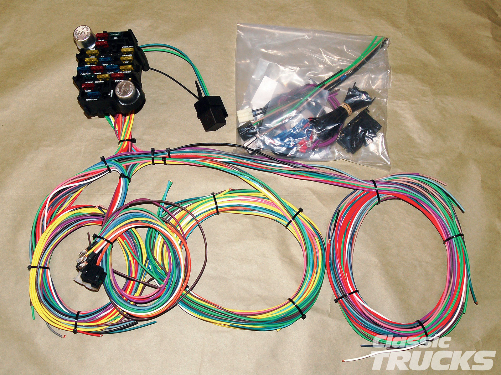
Alright, let's dive into the world of aftermarket automotive wiring harnesses. Whether you're battling a frustrating electrical gremlin, planning a custom modification, or simply want to deepen your understanding of your car's inner workings, knowing how to read and understand these diagrams is crucial. Think of it as the roadmap to your vehicle's nervous system.
Purpose – Why Aftermarket Wiring Diagrams Matter
Unlike factory wiring diagrams which can be quite complex and often proprietary, aftermarket wiring diagrams focus on specific systems or modifications. They're designed to be more user-friendly and cater to the DIY enthusiast. The primary reasons you might need one include:
- Repairs and Troubleshooting: Identifying damaged wires, faulty components, and shorts becomes significantly easier with a clear diagram. Instead of blindly probing with a multimeter, you can trace circuits logically.
- Custom Modifications: Installing aftermarket stereos, lights, alarms, or even engine swaps often requires integrating into the existing wiring. An aftermarket diagram helps you do this safely and correctly.
- Learning and Understanding: Even if you're not actively working on your car, studying these diagrams will enhance your overall knowledge of automotive electrical systems.
- Simplifying Complex Systems: Sometimes, isolating a particular circuit from the factory harness for modification or diagnosis requires a simplified representation. Aftermarket diagrams provide this clarity.
Key Specs and Main Parts
Before we jump into the intricacies of the diagram itself, let's cover some key specifications and components often found in aftermarket harnesses:
- Wire Gauge: This refers to the thickness of the wire, usually expressed in AWG (American Wire Gauge). A lower number indicates a thicker wire, capable of handling more current. Understanding the correct gauge is vital to avoid overheating and potential fires. For example, a 12 AWG wire is suitable for higher current applications like powering amplifiers, while 18 AWG may suffice for indicator lights.
- Wire Color Coding: Standardized color codes are used to identify the function of each wire. While not universally consistent across all manufacturers, common colors like red (power), black (ground), and yellow (ignition) are frequently used. The diagram will usually include a legend explaining the color codes used in that specific harness.
- Connectors: Aftermarket harnesses often use standardized connectors for easy integration. Common types include Deutsch connectors (known for their ruggedness and water resistance), Metri-Pack connectors, and Molex connectors. The diagram will indicate the connector type and pinout (which wire goes to which pin).
- Fuses and Relays: These are essential for circuit protection and control. Fuses protect the wiring from overcurrent, while relays allow a low-current circuit to control a high-current circuit (e.g., using a switch to activate a high-power fuel pump). The diagram will show the location and rating of fuses and relays.
- Grounding Points: Proper grounding is crucial for a stable and reliable electrical system. The diagram will show the recommended grounding points, usually on the vehicle's chassis.
Symbols – Decoding the Diagram
Understanding the symbols used in the diagram is key to interpreting it correctly. Here are some common symbols and their meanings:
- Solid Lines: Represent wires. Thicker lines may indicate higher current-carrying capacity.
- Dashed Lines: Often represent shielded wires or wires that are not part of the main harness but are connected to it.
- Color Codes: Usually abbreviated (e.g., "RD" for red, "BK" for black, "BL" for blue). The diagram's legend will decode these abbreviations.
- Ground Symbol: A series of descending horizontal lines, indicating a connection to the vehicle's chassis (ground).
- Fuse Symbol: A zig-zag line enclosed in a rectangle, often with a number indicating its amperage rating (e.g., "10A" for a 10-amp fuse).
- Relay Symbol: A coil representing the relay's electromagnet, along with switch contacts showing how the relay controls the circuit.
- Connector Symbol: A box or circle with numbers inside, representing the connector pins.
- Component Symbols: Vary depending on the component. Common examples include a light bulb symbol for lights, a speaker symbol for speakers, and a motor symbol for motors.
Lines are crucial for understanding the flow of electricity. Thick solid lines often indicate the main power feed, while thinner lines might represent control signals. The colors, as previously stated, denote the wire's function within the circuit.
How It Works – Tracing the Current Path
The basic principle of an electrical circuit is a closed loop. Current flows from a power source (usually the battery), through various components (switches, fuses, relays, loads), and back to ground, completing the circuit.
To understand how a particular circuit works, start at the power source (often a fuse or the battery positive terminal) and trace the current path through the diagram. Follow the lines, noting the components they pass through and their functions. Pay close attention to switches and relays, as they control the flow of current. The diagram will show the "normal" state of the circuit (e.g., switch open or closed) and how it changes when the switch is activated.
For example, let's say you're tracing the circuit for an aftermarket fog light. You might start at the fuse box, follow the wire through a switch in the cabin, then through a relay in the engine bay, and finally to the fog light itself. The ground wire from the fog light would then connect to the vehicle's chassis.
Real-World Use – Basic Troubleshooting Tips
Here's how you can use an aftermarket wiring diagram to troubleshoot common problems:
- No Power to a Component: Use the diagram to trace the power path from the fuse to the component. Check for blown fuses, open switches, or broken wires along the way. A multimeter can be used to measure voltage at various points to pinpoint the location of the problem.
- Component Always On: This could indicate a short circuit to ground or a stuck relay. Use the diagram to identify potential short circuit locations and check the relay for proper operation.
- Intermittent Problems: These can be the trickiest to diagnose. Carefully inspect the wiring harness for loose connections, corroded terminals, or damaged insulation. Wiggling the wires while monitoring the circuit with a multimeter can help identify the source of the problem.
- Incorrect Wiring: Use the diagram to verify that all wires are connected to the correct terminals and that the wiring matches the intended configuration. A simple error in wiring can lead to unexpected behavior or even damage to the system.
Always remember to disconnect the battery's negative terminal before working on any electrical system. This will prevent accidental shorts and potential damage.
Safety – Highlight Risky Components
Working with automotive electrical systems can be dangerous if proper precautions are not taken. Here are some key safety considerations:
- High Voltage: While the standard automotive system is 12V, some systems, such as those related to ignition, can involve significantly higher voltages. Be extremely cautious when working around these components.
- Short Circuits: A short circuit can cause a large current to flow, potentially damaging wiring, components, and even causing a fire. Always disconnect the battery before working on any electrical system and use appropriate tools to prevent shorts.
- Airbags: Airbag systems are highly sensitive and can deploy unexpectedly if not handled correctly. Consult the vehicle's service manual before working near airbags. Often, disconnecting the battery and waiting a certain amount of time will discharge the system, but always verify.
- Fuel System: Working near the fuel system requires extreme caution. Fuel is highly flammable and can be easily ignited by sparks. Always work in a well-ventilated area and avoid using any tools that could create sparks.
Always prioritize safety. If you are unsure about any aspect of the electrical system, consult a qualified mechanic.
Understanding aftermarket automotive wiring diagrams is a valuable skill for any car enthusiast. By mastering the symbols, tracing the circuits, and following safety precautions, you can confidently tackle electrical repairs and modifications, gaining a deeper understanding of your vehicle's complex systems. By having this tool, you will be able to save time, effort, and money, as well as increasing your own knowledge.
We have an example aftermarket wiring diagram file available for download. Feel free to use it as a practical reference to enhance your understanding of the concepts discussed here. You can examine the example diagram and compare with what you have learned.