
Aftermarket Electric Fan Wiring Diagram
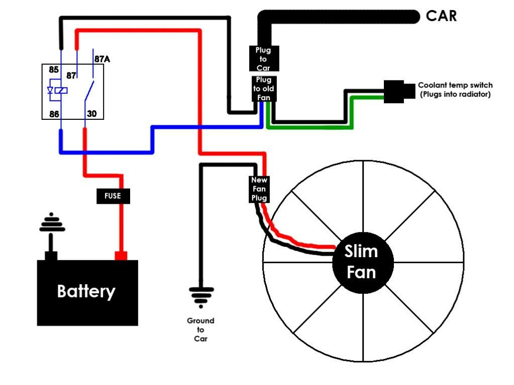
So, you're tackling an aftermarket electric fan install or maybe wrestling with a faulty setup already in place? Understanding the wiring diagram is absolutely critical. It's the roadmap to making sure your engine stays cool without frying your electrical system. This article will break down the typical aftermarket electric fan wiring diagram, empowering you to diagnose issues, make informed decisions, and perform installations with confidence.
Why Bother with the Wiring Diagram?
Think of the wiring diagram as the car's circulatory system chart, but for electricity. It shows how all the components are interconnected. Ignoring it is like performing surgery blindfolded – you might get lucky, but you're far more likely to cause damage. Here's why understanding it matters:
- Troubleshooting: When your fan isn't working correctly (or at all!), the diagram helps you trace the circuit to pinpoint the problem – a blown fuse, a faulty relay, a broken wire, etc.
- Installation: Properly wiring an electric fan is crucial for its longevity and safety. The diagram ensures you connect everything correctly, minimizing the risk of shorts or overheating.
- Modification & Customization: Maybe you want to add a manual override switch, or integrate your fan with a standalone engine management system (EMS). The diagram is your guide to making those modifications safely and effectively.
- Learning: Understanding the diagram is a fantastic way to learn basic automotive electrical principles, which can be applied to other projects.
Key Specs and Main Parts of an Electric Fan Circuit
Let's break down the components you'll typically encounter in an aftermarket electric fan circuit. Keep in mind that diagrams can vary, but these are the common elements:
- Electric Fan(s): The core component. These come in various sizes and CFM (cubic feet per minute) ratings. CFM dictates how much air the fan can move – higher CFM equals more cooling.
- Power Source (Battery): The source of electricity, typically the car's 12V battery. It's crucial to use a properly fused connection directly to the battery (or a distribution block connected to the battery).
- Fuse: A safety device designed to protect the circuit from overcurrent. When the current exceeds a certain limit, the fuse blows (breaks the circuit), preventing damage to the fan, wiring, and other components. The amperage rating of the fuse should be matched to the fan's specifications, slightly higher than the normal operating current, to avoid nuisance trips but low enough to provide protection.
- Relay: An electrically operated switch. A small control signal (e.g., from the temperature sensor or a manual switch) activates the relay, which then closes a high-current circuit to power the fan. Relays are essential because most temperature sensors and switches cannot handle the high current draw of the fan directly.
- Temperature Sensor/Switch: This monitors the engine coolant temperature and triggers the fan when the engine reaches a pre-determined temperature. These can be mechanical (directly inserted into the coolant passage) or electrical (using a sensor and ECU input).
- Wiring: Conductors that carry the electrical current. Wire gauge (thickness) is important! Undersized wires can overheat and cause fires. Use appropriately sized wiring based on the fan's amperage draw and the length of the wire run. A general rule of thumb is to consult an ampacity chart for the specific wire type and insulation temperature rating.
- Ground: A connection back to the chassis of the car, completing the electrical circuit. A good, clean ground is absolutely essential for proper operation.
Decoding the Wiring Diagram: Symbols, Lines, and Colors
Wiring diagrams use standardized symbols to represent different components. Here's a quick guide:
- Straight Lines: Represent wires. Thicker lines often indicate heavier gauge wires (higher current capacity).
- Dashed Lines: Often used for ground connections or connections to optional components.
- Zig-Zag Line: Represents a resistor (used to limit current).
- Circle with an 'M': Represents an electric motor (like the fan motor).
- Rectangle with a diagonal line: Represents a fuse.
- Rectangle with a coil symbol inside: Represents a relay.
- Circle with a 'T': Represents a temperature switch/sensor.
- Ground Symbol (Typically three lines getting shorter): Indicates a connection to the vehicle's chassis ground.
Wire Colors: While not always consistent, certain colors are commonly used:
- Red: Typically used for positive (+) power from the battery.
- Black: Almost always used for ground (-).
- Other Colors (Blue, Green, Yellow, White, etc.): Used for signal wires (e.g., from the temperature sensor to the relay). The specific color code will vary, but the diagram will usually indicate the function of each wire.
Understanding Relay Diagrams: Relays have five main terminals (although some variations exist):
- 30: Power Input (typically directly from the battery, through a fuse).
- 87: Power Output (to the fan).
- 85: Relay Coil Ground.
- 86: Relay Coil Positive (activated by the temperature sensor or switch).
- 87a: Normally Closed Output (often not used in fan circuits, but could be used for a warning light or other function).
How It Works: A Typical Electric Fan Circuit
Here's a simplified explanation of how a typical electric fan circuit operates:
- Power flows from the battery, through a fuse, to terminal 30 on the relay.
- When the engine coolant reaches the set temperature, the temperature sensor/switch closes, providing a ground (or positive) signal to terminal 86 on the relay.
- This activates the relay coil, creating an electromagnetic field that pulls the relay's internal switch closed.
- Closing the relay switch connects terminal 30 (power) to terminal 87, sending power to the electric fan.
- The fan runs, drawing air through the radiator and cooling the engine.
- Once the engine cools down, the temperature sensor/switch opens, deactivating the relay and turning off the fan.
Real-World Use: Basic Troubleshooting Tips
If your fan isn't working, here's a quick troubleshooting process:
- Check the Fuse: This is the first and easiest thing to check. Use a multimeter or a test light to verify continuity. Replace the fuse with the correct amperage rating if it's blown.
- Check the Relay: You can test the relay by swapping it with a known good relay (of the same type). You can also use a multimeter to check for continuity between terminals when the relay is activated. You can also listen for a "click" when the relay is energized.
- Check the Temperature Sensor/Switch: Use a multimeter to check for continuity when the engine is at or above the set temperature. A bad sensor is a common cause of fan failure.
- Check the Wiring: Look for any obvious breaks, corrosion, or loose connections. Use a multimeter to check for voltage at the fan connector when the relay is activated.
- Check the Ground: Ensure the ground connection is clean and tight. A poor ground can cause all sorts of electrical problems.
Safety First: Handle with Care
Working with automotive electrical systems can be dangerous. Here are some important safety precautions:
- Disconnect the Battery: Always disconnect the negative battery terminal before working on any electrical components.
- Use Proper Tools: Use insulated tools and avoid working in wet conditions.
- Be Aware of Hot Wires: Even with the battery disconnected, capacitors can hold a charge. Exercise caution when working with wiring, especially near the ECU.
- Don't Exceed Circuit Ratings: Never use a fuse with a higher amperage rating than specified for the circuit.
- Double-Check Your Work: Before reconnecting the battery, carefully review your wiring to ensure everything is connected correctly.
A final important point: Working with the vehicles' electrical system can be risky. If you do not have the skill, tools, and/or knowledge, it is always best to seek help from a trained professional.
Armed with this knowledge, you're well-equipped to understand and troubleshoot your aftermarket electric fan wiring. And remember, a detailed wiring diagram specific to *your* fan setup is invaluable.
We have a generic aftermarket electric fan wiring diagram file available for download. It will provide a visual aid for you. Please remember to always refer to your fan's manufacturer's specifications for wiring best practices.