
Aftermarket Electric Fan Wirng Diagram
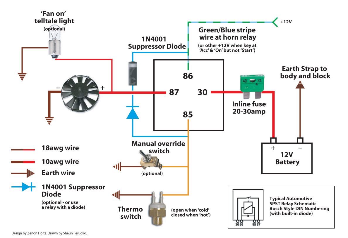
So, you're looking to upgrade or repair your electric cooling fan system? Smart move. Electric fans can free up horsepower, improve fuel economy, and offer more precise temperature control than their mechanical counterparts. This article is your comprehensive guide to understanding aftermarket electric fan wiring diagrams, helping you navigate the often-intimidating world of automotive electrical systems. We'll break down the key components, explain the symbols you'll encounter, and equip you with the knowledge to install or troubleshoot your system with confidence.
Purpose: Decoding the Electric Fan Wiring Diagram
Why bother with a wiring diagram? Because electrical gremlins are notoriously difficult to hunt down without one. A clear and accurate diagram is essential for several reasons:
- Installation: Whether you're adding an aftermarket fan for better cooling or replacing a faulty one, the diagram shows you exactly where each wire needs to go. No more guessing!
- Troubleshooting: If your fan isn't working correctly, the diagram helps you systematically trace the circuit to identify the problem (e.g., a blown fuse, a faulty relay, or a broken wire).
- Modification: Want to add a manual override switch or adjust the fan's operating temperature? The diagram provides the roadmap for safe and effective modifications.
- Learning: Understanding how the system is designed and wired will significantly enhance your understanding of automotive electrical systems in general.
Key Specs and Main Parts of an Electric Fan System
Before diving into the diagram, let's familiarize ourselves with the key components:
- Electric Fan: The heart of the system. It's a DC motor that pulls air through the radiator to cool the engine. Specs to note include voltage (usually 12V), amperage draw (important for sizing fuses and relays), and CFM (Cubic Feet per Minute) rating, which indicates airflow.
- Temperature Sensor (Thermostat): This device monitors the coolant temperature. When the temperature reaches a preset threshold, the sensor closes a circuit, signaling the fan to turn on. Some systems use adjustable thermostats for customized control.
- Relay: A relay is an electrically operated switch. Because electric fans draw a significant amount of current, a relay is used to protect the sensitive circuits of the temperature sensor and ignition switch. The sensor triggers the relay, which then supplies the high current needed to power the fan. Common relays are 4-pin or 5-pin SPST (Single Pole Single Throw) or SPDT (Single Pole Double Throw).
- Fuse: A safety device designed to protect the circuit from overcurrent. If the current exceeds the fuse's rating, the fuse blows, interrupting the circuit and preventing damage to the wiring and components. Choosing the correct amperage fuse is critical.
- Wiring: The conductors that connect all the components. Wire gauge (thickness) is crucial; using too thin a wire can cause voltage drop and overheating, potentially leading to a fire. Automotive wiring is typically stranded copper.
- Ground Connection: Every electrical circuit needs a ground. This is a connection to the vehicle's chassis, providing a return path for the current. A good, clean ground is essential for proper operation.
- Optional Components: These can include manual override switches, fan controllers with variable speed control, and warning lights to indicate fan operation.
Symbols: Deciphering the Wiring Diagram Language
Wiring diagrams use a standardized set of symbols to represent electrical components and connections. Here's a breakdown of some common symbols you'll encounter in an electric fan wiring diagram:
- Solid Lines: Represent wires. The thickness of the line doesn't necessarily indicate wire gauge, although sometimes diagrams will use thicker lines for higher current wires.
- Dashed Lines: Often indicate wires or connections that are optional or only present in certain configurations.
- Circles: Can represent various components, depending on what's inside. A circle with a resistor symbol inside represents a resistor.
- Rectangles: Often represent switches, relays, or control modules.
- Zigzag Line: Represents a resistor.
- Coil Symbol (Curly Line): Represents an inductor, often found inside relays.
- Triangle Pointing to a Line: Represents a diode.
- Ground Symbol (Stacked Horizontal Lines): Indicates a connection to the vehicle's chassis ground.
- Battery Symbol (Long and Short Parallel Lines): Represents the battery, the source of power for the system.
- Fuse Symbol (S-Shaped Line): Represents a fuse. Sometimes it's a rectangle with a wavy line inside.
- Relay Symbol: Usually a rectangle with a coil symbol inside, and labeled with terminals (e.g., 30, 85, 86, 87, 87a). These numbers refer to the standard relay pin assignments.
Color Coding: Wire colors are crucial for identification. Diagrams usually indicate the color of each wire using abbreviations (e.g., RED, BLU, GRN, YEL, BLK). Standard automotive wiring color codes are generally followed, but it's always best to double-check the diagram.
How It Works: Tracing the Circuit
Let's trace a typical electric fan circuit to understand how it operates.
- Power Source: The circuit begins at the battery (positive terminal).
- Fuse Protection: A fuse is placed in the circuit to protect against overcurrent.
- Relay Activation: Power flows to the relay. Typically, power is supplied to terminal 30.
- Temperature Sensor Control: The temperature sensor acts as a switch. When the coolant temperature reaches the set point, the sensor closes the circuit, providing a ground path to the relay coil (typically terminal 85). Terminal 86 usually gets power from an ignition switched source.
- Relay Operation: When the relay coil is energized (power and ground are present), it creates an electromagnetic field, which pulls the relay's internal switch closed.
- Fan Power: This closed switch connects the high-current power from terminal 30 to terminal 87, providing power to the electric fan motor.
- Ground Return: The fan motor is connected to ground, completing the circuit and causing the fan to spin.
- Fan Operation Cycle: When the coolant temperature drops below the set point, the temperature sensor opens the circuit, de-energizing the relay coil. The relay switch opens, cutting power to the fan, and the fan stops. This cycle repeats to maintain the desired coolant temperature.
Some systems include a manual override switch. This switch bypasses the temperature sensor and provides a direct ground to the relay coil, allowing you to turn the fan on manually, regardless of the coolant temperature.
Real-World Use: Basic Troubleshooting Tips
Here are some basic troubleshooting tips using the wiring diagram as your guide:
- Fan Not Working:
- Check the Fuse: The simplest and most common cause. Replace the fuse with one of the same amperage rating.
- Test the Relay: You can often swap the relay with a known good relay (e.g., from the horn) to see if that solves the problem. You can also test the relay using a multimeter to check for continuity and proper operation.
- Inspect Wiring and Connections: Look for loose connections, corroded terminals, or damaged wires. Pay particular attention to ground connections.
- Test the Temperature Sensor: Use a multimeter to check for continuity when the coolant temperature is above the set point. If there's no continuity, the sensor is likely faulty.
- Check Fan Motor: Apply direct power and ground to the fan motor to see if it spins. If not, the motor is likely bad.
- Fan Runs Constantly:
- Check the Temperature Sensor: It may be stuck in the closed position, constantly providing a ground to the relay.
- Check the Relay: The relay contacts may be stuck in the closed position.
- Wiring Short: There may be a short circuit in the wiring, providing a constant ground to the relay coil.
Always use a multimeter to safely test for voltage and continuity before making any connections or disconnections.
Safety: Working with Automotive Electrical Systems
Working with automotive electrical systems can be dangerous if you're not careful. Here are some important safety precautions:
- Disconnect the Battery: Always disconnect the negative battery terminal before working on any electrical component. This prevents accidental short circuits and potential shocks.
- Use Proper Tools: Use insulated tools specifically designed for automotive electrical work.
- Wear Safety Glasses: Protect your eyes from sparks and debris.
- Avoid Water: Never work on electrical systems in wet conditions.
- Fuse Ratings: Never replace a fuse with one of a higher amperage rating. This can overload the circuit and cause a fire.
- Working with Relays: Relays can get hot during operation. Avoid touching them immediately after the fan has been running.
- High Current: Electric fans draw significant current, so ensure your wiring is properly sized to handle the load. Undersized wiring can overheat and melt, potentially causing a fire.
The battery and the starter solenoid are capable of supplying very high amperage that can cause burns. Be extremely cautious when working around these components.
With the knowledge gained from this guide and a reliable wiring diagram, you're well-equipped to tackle your electric fan project. Understanding the purpose of each component, how they interact, and the potential pitfalls will ensure a safe and successful outcome.
Now that you understand the basics, you'll need a specific wiring diagram for your particular electric fan and vehicle configuration. We have a library of common aftermarket electric fan wiring diagrams available for download. Please contact us to obtain the right diagram for your specific needs.