
Aftermarket Radio Wiring Harness Diagram
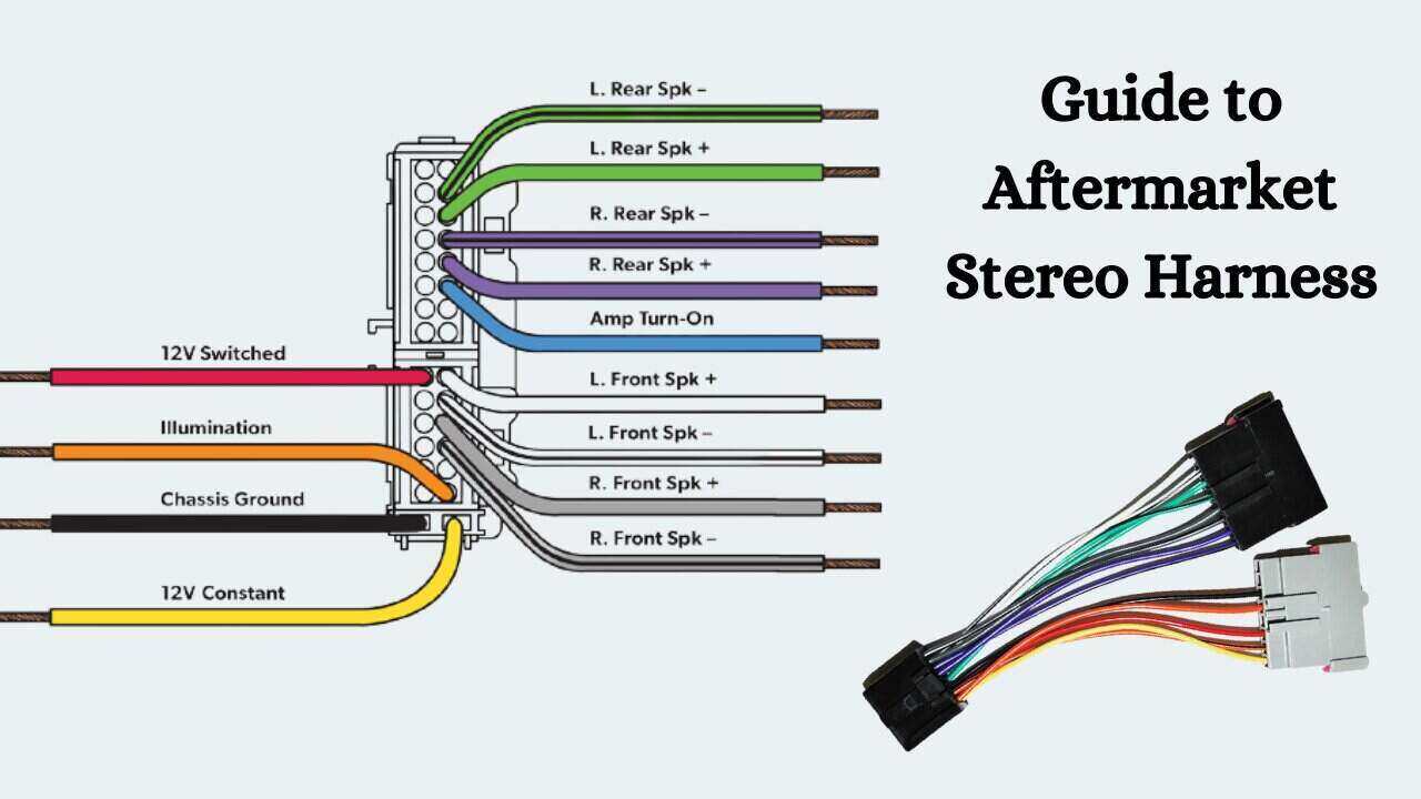
So, you're diving into the world of aftermarket radio installations, huh? Excellent choice. Upgrading your car's audio system can breathe new life into your ride, and a crucial piece of the puzzle is understanding the aftermarket radio wiring harness diagram. This document, often overlooked, is the Rosetta Stone for connecting your new head unit without butchering your factory wiring. This article will serve as a comprehensive guide to demystify these diagrams, empowering you to install your aftermarket radio with confidence and expertise.
Why This Diagram Matters
Let's be honest: staring at a mess of wires without a guide is a recipe for disaster. The aftermarket radio wiring harness diagram offers several critical advantages:
- Simplified Installation: The diagram clearly shows which wire from your aftermarket radio needs to connect to which wire in your vehicle's wiring harness. This eliminates guesswork and reduces the risk of incorrect connections.
- Preventing Damage: Incorrect wiring can damage your car's electrical system, the radio itself, or even worse, trigger safety systems. The diagram helps you avoid these costly mistakes.
- Easy Troubleshooting: If something goes wrong after the installation (no power, no sound, etc.), the diagram is invaluable for troubleshooting. You can systematically check each connection to identify the source of the problem.
- Maintaining Resale Value: A clean, professional installation, thanks to the correct use of a harness and wiring diagram, preserves your car's electrical integrity and helps maintain its resale value. No one wants to buy a car with a hacked-up wiring harness.
- Learning Opportunity: Even if you're paying someone else to do the installation, understanding the wiring diagram gives you a deeper understanding of your car's electrical system.
Key Specs and Main Parts
A typical aftermarket radio wiring harness diagram will represent the following key components and specifications:
- Power Wires: These are the most crucial. You'll typically find:
- +12V Constant (Battery): Provides constant power to the radio for memory functions (clock, presets, etc.).
- +12V Switched (Ignition): Provides power only when the ignition is on, turning the radio on and off with the car.
- Ground: The return path for the electrical current.
- Speaker Wires: These wires connect to the speakers in your car. Each speaker requires two wires: positive (+) and negative (-). The diagram will typically show which wire goes to which speaker (front left, front right, rear left, rear right).
- Antenna Wire: Connects to the car's antenna.
- Illumination Wire: Dims the radio's display when the headlights are turned on.
- Remote Turn-On (Amplifier Remote): Sends a +12V signal to turn on an external amplifier when the radio is turned on.
- Steering Wheel Control Wires: Allows you to control the radio using the buttons on your steering wheel (requires a separate adapter in most cases).
- Reverse Wire: Sends a signal (typically +12V) when the car is in reverse, which can be used to trigger a backup camera.
- Mute Wire: Used to mute the radio when receiving a phone call (usually found in radios with Bluetooth).
- Wire Gauge: The thickness of the wire, usually expressed in AWG (American Wire Gauge). Using the correct gauge is crucial to prevent overheating and potential fires. Typically, power wires are thicker (lower AWG number) than speaker wires.
- Fuse Rating: Indicates the size of the fuse that protects the radio. Using a fuse with a higher rating can damage the radio.
Understanding the Symbols
Wiring diagrams use specific symbols and conventions to represent different components and connections. Understanding these symbols is key to interpreting the diagram correctly.
- Lines: Lines represent wires. Solid lines typically indicate a direct connection, while dashed lines may indicate a connection that is optional or depends on the specific vehicle.
- Colors: Each wire is typically assigned a specific color. The diagram will include a legend that shows which color corresponds to which function. Common colors include red (power), black (ground), yellow (constant power), blue (remote turn-on), and various colors for speakers. Always double-check the color coding against your actual wires, as manufacturers sometimes deviate.
- Icons: Certain icons may be used to represent components such as fuses, resistors, capacitors, and diodes.
- Connector Symbols: Diagrams will show how the wires terminate in the connector that plugs into the factory harness. Pay attention to the pin numbers, if shown, to ensure you're connecting the wires to the correct pins.
How It Works
The wiring harness diagram acts as a roadmap for connecting your aftermarket radio. It bridges the gap between the proprietary wiring of your new radio and the standardized wiring of your car. The adapter harness is designed to plug into the factory harness, providing a clean and reversible connection. You then connect the wires from the adapter harness to the corresponding wires from your aftermarket radio's wiring harness, following the diagram's instructions. This involves matching the colors and functions of the wires, ensuring that power, ground, speakers, and other signals are correctly routed.
The crucial thing is matching the function, not just the color. Some cars may have slightly different color schemes for the same function, so rely on the diagram as the ultimate source of truth.
Real-World Use: Basic Troubleshooting Tips
Even with a diagram, things can sometimes go wrong. Here are some common issues and how to troubleshoot them using the diagram:
- No Power: Check the +12V constant and +12V switched connections. Use a multimeter to verify that you have voltage at these wires when the ignition is on (for the switched wire) and off (for the constant wire). Also, check the fuse on the radio and in the car's fuse box.
- No Sound: Verify the speaker connections. Make sure the positive and negative wires are connected to the correct terminals on the speakers. Check the balance and fader settings on the radio to ensure the sound isn't being routed to only one speaker.
- Radio Resets or Loses Memory: The +12V constant wire is not properly connected or has a bad connection.
- Excessive Noise or Interference: Ensure the ground connection is solid. A poor ground can introduce noise into the audio signal. Check the antenna connection and make sure it's properly seated.
- Steering Wheel Controls Not Working: The steering wheel control adapter is not properly programmed or connected. Consult the adapter's documentation for troubleshooting steps.
Safety First!
Working with car electrical systems can be dangerous if you're not careful. Here are some crucial safety precautions:
- Disconnect the Battery: Always disconnect the negative terminal of the car battery before working on the electrical system. This prevents accidental short circuits and potential electrical shocks.
- Use Proper Tools: Use insulated tools to avoid short circuits. Crimping tools, wire strippers, and a multimeter are essential.
- Avoid Working on Live Wires: Never work on wires with the battery connected.
- Protect Your Eyes: Wear safety glasses to protect your eyes from flying debris.
- Be Aware of Airbag Wires: Airbag systems are very sensitive, and tampering with their wiring can cause them to deploy unexpectedly. Consult your car's service manual before working near airbag components. It is always recommended to have a professional handle any work on SRS systems.
- Be cautious when testing for voltage. The +12V Constant (Battery) is always hot and could cause a short.
We have prepared a generic Aftermarket Radio Wiring Harness Diagram to help get you started on your project. You can download the file here.