Aftermarket Radio Wiring Harness With Oem Plug
So, you're looking to upgrade your car's audio system? Excellent! One of the most crucial, yet sometimes daunting, steps in that process is connecting the new aftermarket radio to your vehicle's electrical system. This is where the aftermarket radio wiring harness with an OEM (Original Equipment Manufacturer) plug comes into play. We're going to break down everything you need to know about these harnesses, from their purpose and specs to troubleshooting and safety. Understanding this wiring is critical not just for audio upgrades, but also for troubleshooting existing radio issues, learning about your car's electrical system, or even diagnosing a blown fuse.
Purpose and Benefits
The primary purpose of an aftermarket radio wiring harness with an OEM plug is to provide a clean and safe interface between your new radio and your car's existing wiring. Instead of cutting and splicing the factory wires – a messy and often unreliable method – the harness plugs directly into the OEM radio connector in your dashboard. This plug and play solution provides several benefits:
- Simplified Installation: No need to identify and splice individual wires. The harness provides color-coded wires that correspond to the functions of your new radio.
- Reversibility: If you ever want to reinstall the factory radio or sell the car, you can easily unplug the harness and reconnect the original radio without any permanent modifications.
- Prevents Damage: Cutting factory wiring can void your car's warranty or cause electrical problems. Using a harness eliminates this risk.
- Clean and Professional Look: A well-installed harness keeps your wiring organized and prevents a tangled mess behind the dashboard.
Key Specs and Main Parts
Let's dive into the anatomy of a typical aftermarket radio wiring harness.
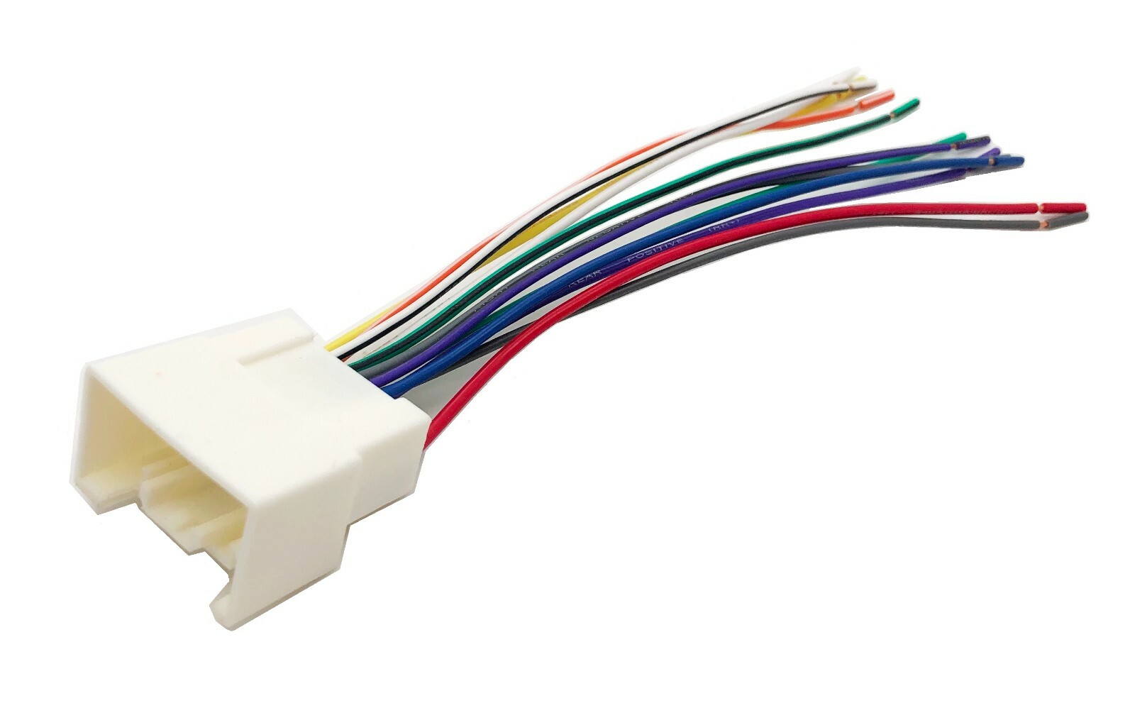
- OEM Connector: This is the part that plugs directly into your car's factory radio connector. It's usually a molded plastic piece with pins that match the exact configuration of your car's wiring.
- Aftermarket Radio Connector: This connector plugs into the back of your new radio. The standard is usually an ISO connector.
- Color-Coded Wires: These wires connect the OEM connector to the aftermarket radio connector and are color-coded according to industry standards to indicate their function (e.g., power, ground, speakers, etc.). The Electronic Industries Alliance (EIA) has established a universal color coding scheme.
- Fuse: Most harnesses include a fuse inline with the 12V constant (battery) wire. This protects both the radio and your car's electrical system from overloads. A common fuse value is 10 amps.
- Antenna Adapter (Optional): Some cars require an antenna adapter to connect the aftermarket radio's antenna input to the car's antenna cable.
- Steering Wheel Control Adapter (Optional): If you want to retain your steering wheel controls with your new radio, you'll need a separate adapter that connects to the harness.
Important Specs:
- Wire Gauge: The wire gauge (thickness) is important for carrying the necessary current. 16 or 18 gauge wire is typically used for speaker wires, while 14 or 16 gauge is common for power and ground.
- Voltage Rating: Ensure the harness is rated for at least 12V DC, which is the standard voltage in automotive electrical systems.
- Fuse Rating: The fuse rating should match the recommendations of both the car's manual and the radio manufacturer.
Understanding the Wiring Diagram: Symbols, Colors, and Icons
A wiring diagram is your roadmap to connecting the harness correctly. Here's a breakdown of common symbols and conventions:
- Lines: Solid lines represent wires. Dashed lines often indicate shielded cables or wires that are optional or only present in certain vehicles.
- Colors: Each wire is assigned a specific color, and the diagram will include a key that explains the color codes. Common colors include red (12V constant), yellow (12V switched), black (ground), white (front left speaker +), gray (front right speaker +), green (rear left speaker +), and purple (rear right speaker +). These are *general* guidelines and may vary. Always double-check.
- Icons: Icons represent components like fuses, connectors, resistors, and other electrical parts. A simple rectangle might represent a fuse, while a circle with a line through it often represents a ground connection.
- Abbreviations: You might see abbreviations like "ACC" for accessory (switched power), "GND" for ground, "BAT" for battery (constant power), "REM" for remote turn-on (for amplifiers), and "ILL" for illumination.
Example Color Codes and their Functions:
- Red: 12V Constant (Battery) - Provides power to the radio even when the ignition is off, for memory functions.
- Yellow: 12V Switched (Ignition/Accessory) - Provides power only when the ignition is on or in the accessory position.
- Black: Ground - Completes the electrical circuit.
- White/White-Black: Front Left Speaker (+/-)
- Gray/Gray-Black: Front Right Speaker (+/-)
- Green/Green-Black: Rear Left Speaker (+/-)
- Purple/Purple-Black: Rear Right Speaker (+/-)
- Blue: Remote Turn-On - Used to activate external amplifiers.
- Orange: Illumination - Dims the radio display when the headlights are turned on.
How It Works
The wiring harness acts as a translator between your car's electrical system and your new radio. It takes the signals from the car's OEM connector (power, ground, speaker outputs, etc.) and translates them into a format that your aftermarket radio can understand. When you plug the OEM connector into the car's wiring, the harness connects the corresponding wires to the aftermarket radio connector. This allows the radio to receive power, ground, and speaker signals without you having to cut or splice any wires. The most important part is matching the wire functions. For instance, the harness's red wire (12V constant) connects to the car's wire that provides constant 12V power, ensuring the radio retains its memory settings. Similarly, the speaker wires are connected to the corresponding speaker outputs in the car.
Real-World Use and Basic Troubleshooting
Even with a wiring harness, problems can arise. Here are some common issues and how to troubleshoot them:
- Radio Not Turning On:
- Check the fuse in the harness. If it's blown, replace it with one of the same amperage.
- Verify that the 12V constant (red) and 12V switched (yellow) wires are receiving power. Use a multimeter to check for 12V DC.
- Ensure the ground (black) wire is properly grounded.
- No Sound:
- Double-check that all speaker wires are connected correctly. Pay attention to polarity (+/-).
- Make sure the radio's fader and balance settings are properly adjusted.
- If you're using an external amplifier, verify that the remote turn-on (blue) wire is connected and functioning.
- Radio Turns Off Intermittently:
- Check for loose connections in the harness.
- Inspect the car's wiring for any signs of damage or corrosion.
- A weak battery or a faulty alternator can also cause intermittent power issues.
- Steering Wheel Controls Not Working:
- Ensure the steering wheel control adapter is properly programmed and connected.
- Check the adapter's instructions for specific troubleshooting steps.
Safety First!
Working with automotive electrical systems can be dangerous if proper precautions are not taken. Always disconnect the car's negative battery terminal before working on any electrical components. This prevents accidental shorts and potential damage to your car's electrical system or the radio. Identify the 12V constant wire. Accidentally grounding this wire can create a short circuit and potentially start a fire. Also, pay attention to the airbag system in your car, as interfering with airbag wiring can cause them to deploy unexpectedly. If you are not comfortable working with electrical systems, consult a professional.
Remember, double-checking your connections and verifying the wire functions with a multimeter is always a good practice before plugging in your new radio. A small mistake can lead to a big headache!
We have a comprehensive wiring diagram available for download to assist you with your installation. The diagram details each wire connection and color code for a wide variety of vehicles. This resource will be invaluable as you navigate your radio upgrade project.