Aftermarket Turn Signal Switch Wiring Diagram
So, you're staring down a tangled mess of wires, trying to figure out your aftermarket turn signal switch wiring? Whether you're upgrading an old classic, installing a new steering column, or troubleshooting a wonky system, understanding the turn signal switch wiring diagram is absolutely crucial. This article will break down the anatomy of these diagrams, explain how they work, and give you the knowledge to tackle your project with confidence. We're aiming for clarity here, like having a conversation with a mechanic who knows their stuff but isn't trying to blind you with jargon.
Purpose: Decoding the Electrical Language of Turns
Why is a turn signal wiring diagram so important? The answer is multifaceted:
- Repair and Diagnostics: When your turn signals malfunction, the wiring diagram is your roadmap for pinpointing the problem. It allows you to trace circuits, check for continuity, and identify faulty components.
- Customization and Upgrades: Installing an aftermarket steering column, steering wheel, or turn signal switch often requires rewiring. The diagram ensures you connect everything correctly and avoid short circuits.
- Understanding Vehicle Electrical Systems: Even if you're not actively working on your turn signals, studying the diagram provides valuable insight into how automotive electrical systems function in general.
- Restoration Projects: Classic car restorations often involve dealing with deteriorated or modified wiring. A diagram helps you restore the system to its original configuration or integrate modern components safely.
Key Specs and Main Parts: The Players in the Circuit
Before diving into the diagram itself, let's identify the key players:
- Turn Signal Switch: The heart of the system. It directs power to the appropriate left or right turn signals. Modern switches are often multi-functional, incorporating features like hazard lights and dimmer controls.
- Flasher Unit (or Relay): This device interrupts the current flow to the turn signals, creating the characteristic flashing effect. There are two primary types: thermal flashers, which use a bimetallic strip, and electronic flashers, which use transistors and integrated circuits for more reliable operation.
- Turn Signal Bulbs: These are the visual indicators of your intended turn. Typically incandescent bulbs in older vehicles, and increasingly LEDs in newer ones.
- Hazard Light Switch: Activates all turn signals simultaneously. It often bypasses the turn signal switch circuitry but uses the same flasher unit.
- Wiring Harness: The collection of wires that connects all the components. Each wire is usually color-coded for easy identification.
- Fuse: A safety device designed to protect the circuit from overcurrent. A blown fuse indicates a problem in the circuit.
- Ground (Chassis Ground): The electrical return path for the circuit. Usually, the negative terminal of the battery is connected to the vehicle's chassis, providing a common ground point.
Symbols: Deciphering the Code
Understanding the symbols used in a turn signal switch wiring diagram is crucial for accurate interpretation. Here's a breakdown of common symbols:
- Solid Lines: Represent wires. The thickness of the line generally doesn't indicate wire gauge unless specifically noted.
- Dashed Lines: May indicate a shielded wire, a connector, or a path that's only active under certain conditions. Consult the specific diagram's legend for clarification.
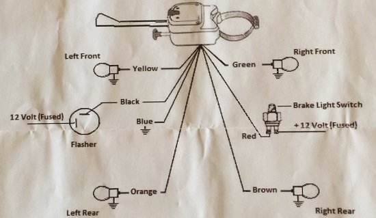
- Color Codes: Wires are typically identified by color abbreviations (e.g., BLK for black, RED for red, GRN for green, YEL for yellow, BLU for blue, WHT for white). Some diagrams may use full color names.
- Circles: Often represent connection points or terminals.
- Rectangles: Can represent various components, such as switches, relays, or electronic modules. The specific function is usually labeled within the rectangle.
- Zigzag Line: Represents a resistor.
- Ground Symbol: Indicates a connection to the vehicle's chassis ground. The symbol typically looks like a series of lines decreasing in length, resembling an upside-down Christmas tree.
- Fuse Symbol: Represents a fuse, typically shown as a line with a small "S" curve in the middle.
- Bulb Symbol: Represents a light bulb, usually drawn as a circle with a cross inside.
- Switch Symbol: Illustrates the contacts of the switch and how they connect in different positions (e.g., left turn, right turn, off).
How It Works: Tracing the Flow of Electricity
The basic operation of a turn signal circuit is relatively straightforward:
- When the ignition switch is turned on, power is supplied to the flasher unit.
- When the turn signal switch is activated (e.g., to signal a left turn), it connects the flasher unit to the left turn signal bulbs.
- The flasher unit interrupts the current flow, causing the bulbs to flash on and off.
- The current flows through the bulbs and back to the ground, completing the circuit.
- The hazard light switch, when activated, bypasses the turn signal switch and connects the flasher unit to all four turn signal bulbs simultaneously.
Let's consider a simplified example. Imagine a wire (e.g., a green wire) runs from the flasher unit to the turn signal switch. When you move the lever to "left turn," the switch internally connects that green wire to another wire (e.g., a yellow wire) that leads to the left front and rear turn signal bulbs. The flasher unit interrupts the power, causing the yellow wire – and therefore the bulbs – to flash. The current then returns to ground through a separate ground wire connected to the bulb housing.
Real-World Use: Basic Troubleshooting Tips
Now, let's say your turn signals aren't working properly. Here are some basic troubleshooting steps, using the wiring diagram as your guide:
- Check the Fuse: This is always the first step. A blown fuse is a common cause of turn signal failure. Consult your vehicle's owner's manual to locate the turn signal fuse and replace it with the correct amperage rating.
- Inspect the Bulbs: A burned-out bulb will prevent that side's turn signals from working. Check both the front and rear bulbs.
- Test the Flasher Unit: If all the bulbs are good and the fuse is intact, the flasher unit may be faulty. You can usually test it by swapping it with a known-good flasher unit (if you have one) or by using a multimeter to check for proper voltage and continuity.
- Check the Turn Signal Switch: Use a multimeter to check for continuity through the switch in each position (left turn, right turn, off). A lack of continuity indicates a faulty switch.
- Inspect the Wiring: Look for damaged, corroded, or loose wires and connectors. Pay particular attention to ground connections, as a poor ground can cause all sorts of electrical problems. Use a multimeter to check for continuity between different points in the circuit.
For example, if your left turn signal isn't working, but your right turn signal is, start by checking the left turn signal bulbs and the wiring leading to them. If those are fine, suspect the turn signal switch contacts for the left turn position.
Safety: Respect the Electrons
Working with automotive electrical systems can be dangerous if you're not careful. Here are some safety precautions:
- Disconnect the Battery: Before working on any electrical component, disconnect the negative terminal of the battery to prevent accidental short circuits.
- Use Proper Tools: Use insulated tools to avoid electrical shock.
- Don't Modify Wiring Unnecessarily: Stick to the wiring diagram as much as possible. If you need to make modifications, do so carefully and use high-quality connectors and wiring.
- Protect Sensitive Components: Some components, such as the flasher unit and any electronic control modules, are sensitive to static electricity. Use anti-static precautions when handling these components.
- Fuses are Crucial: Never bypass a fuse or use a fuse with a higher amperage rating than specified. Fuses protect the wiring from overheating and potentially causing a fire.
The flasher unit and any associated control modules are particularly sensitive to voltage spikes and reversed polarity. Always double-check your wiring before connecting the battery.
Understanding your aftermarket turn signal switch wiring diagram is the key to successful repairs, upgrades, and modifications. By familiarizing yourself with the components, symbols, and troubleshooting techniques, you can confidently tackle your project and keep your turn signals blinking bright.
We have a downloadable file containing a generic aftermarket turn signal switch wiring diagram available for your reference. This diagram provides a general overview and can be used as a starting point for your specific application. Keep in mind that wiring configurations can vary depending on the manufacturer and the specific features of the switch. Be sure to always compare the generic diagram with your specific switch's documentation to ensure accurate wiring.