
Air Compressor Pressure Switch Diagram
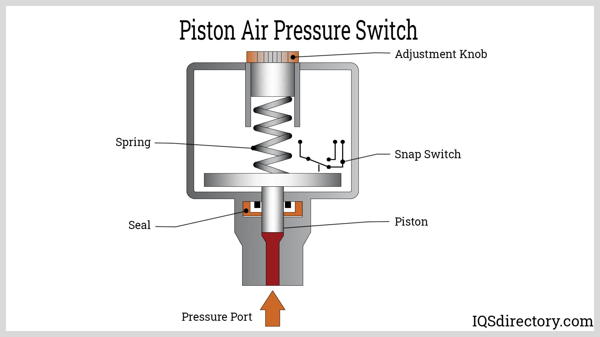
Hey gearheads! Ever wondered how your air compressor *magically* knows when to stop filling the tank? Or maybe you're wrestling with a compressor that's over-pressurizing or refusing to shut off. Chances are, the culprit is lurking within the pressure switch. This article is your deep dive into the pressure switch diagram, breaking down its secrets so you can confidently diagnose, repair, and maybe even upgrade your air compressor.
Why Understanding the Pressure Switch Diagram Matters
Think of the pressure switch as the brain of your air compressor's pressure regulation system. It's a critical component that ensures your tank stays within safe operating parameters. Understanding the pressure switch diagram is invaluable for several reasons:
- Troubleshooting: Diagnosing issues like compressors that won't turn on, won't turn off, or are cycling erratically becomes much easier.
- Repair: You can pinpoint faulty wiring, damaged contacts, or even a malfunctioning switch itself, allowing for targeted repairs.
- Upgrades/Modifications: If you're considering upgrading your compressor, like adding a larger tank or modifying the pressure settings, understanding the switch's wiring is essential.
- General Knowledge: It's simply good to know how things work! This knowledge empowers you to better maintain your equipment and avoid costly professional repairs.
Key Specs and Main Parts
Before we dissect the diagram, let's familiarize ourselves with the key specs and components of a typical air compressor pressure switch.
Key Specs:
- Cut-In Pressure: The pressure at which the compressor starts filling the tank. Usually measured in PSI (pounds per square inch).
- Cut-Out Pressure: The pressure at which the compressor stops filling the tank. Also measured in PSI.
- Differential: The difference between the cut-out and cut-in pressure. This prevents rapid cycling of the compressor.
- Voltage and Amperage Rating: The switch's capacity to handle the electrical load of the motor. Never exceed this rating!
- Number of Poles and Throws: Describes the switch's electrical configuration (e.g., Single Pole Single Throw - SPST, Single Pole Double Throw - SPDT). Most compressor switches are either SPST or Double Pole Single Throw (DPST).
Main Parts:
- Pressure Sensing Element: Usually a diaphragm or piston that reacts to changes in air pressure.
- Switch Contacts: Electrical contacts that open or close to control the motor circuit.
- Leverage Mechanism: A system of levers and springs that translates the pressure from the sensing element into mechanical movement to operate the switch contacts.
- Adjustment Screws: Screws that allow you to adjust the cut-in and cut-out pressure settings. Adjust with caution and proper tools!
- Unloader Valve Connection: A small valve that releases pressure from the compressor head when the motor shuts off, making it easier to start the motor next time.
- Electrical Terminals: Connection points for the power wires going to and from the motor.
Decoding the Diagram: Lines, Colors, and Icons
The pressure switch diagram is essentially a roadmap of the electrical circuit within the switch. Here's what you need to know to read it:
- Solid Lines: Represent electrical wires.
- Dotted Lines: Often indicate mechanical linkages or pneumatic connections (like the air line to the tank).
- Colors: Standard electrical wiring colors are typically used:
- Black (BLK): Hot or live wire.
- White (WHT): Neutral wire.
- Green (GRN): Ground wire.
- Red (RED): Often used for switched power or control circuits.
- Switch Symbols:
- A simple switch is usually represented by a line broken by a gap. An arrow indicates the switching action.
- A normally open (NO) contact means the circuit is open (off) until the switch is activated (pressure reaches cut-in).
- A normally closed (NC) contact means the circuit is closed (on) until the switch is activated (pressure reaches cut-out).
- Other Symbols: You might see symbols for:
- Fuse (F): A safety device that protects the circuit from overcurrent.
- Motor (M): The air compressor motor.
- Ground (GND): Connection to earth ground for safety.
The diagram will clearly show which terminals are connected to the power source (usually labeled L1 and L2 for 240V, or L and N for 120V) and which terminals are connected to the motor. It will also illustrate how the switch contacts open and close based on pressure changes.
How It Works: The Pressure Switch in Action
Here's a step-by-step breakdown of how the pressure switch controls the air compressor:
- Initial State: The tank pressure is below the cut-in pressure. The switch contacts are closed (in the NO configuration), allowing power to flow to the motor.
- Compressor Running: The motor starts and the compressor pumps air into the tank, increasing the pressure.
- Cut-Out Pressure Reached: When the tank pressure reaches the cut-out pressure, the pressure sensing element activates the leverage mechanism, which opens the switch contacts.
- Motor Stops: The power to the motor is cut, and the compressor stops filling the tank. The unloader valve releases pressure from the compressor head.
- Pressure Drops: As you use compressed air, the tank pressure gradually decreases.
- Cut-In Pressure Reached: When the tank pressure drops to the cut-in pressure, the pressure sensing element deactivates the leverage mechanism, closing the switch contacts.
- Cycle Repeats: The motor starts again, and the cycle repeats.
The differential between the cut-in and cut-out pressures is crucial. A small differential would cause the compressor to cycle on and off frequently, leading to excessive wear and tear on the motor. A large differential would result in significant pressure fluctuations in the tank.
Real-World Use: Basic Troubleshooting Tips
Armed with your understanding of the pressure switch diagram, here are a few basic troubleshooting tips:
- Compressor Won't Turn On:
- Check the power supply to the compressor.
- Inspect the fuse or circuit breaker.
- Use a multimeter to check for voltage at the pressure switch terminals. If there's voltage *going* to the switch but not *coming out* when the tank pressure is low, the switch is likely faulty.
- Compressor Won't Turn Off:
- The pressure switch might be stuck in the "on" position. Try tapping it gently.
- The diaphragm or piston in the sensing element might be damaged.
- The switch contacts might be welded together.
- Erratic Cycling:
- The cut-in and cut-out pressure settings might be too close together.
- The unloader valve might be malfunctioning, causing excessive pressure buildup in the compressor head.
- The pressure switch itself might be worn out or damaged.
Always disconnect the power to the compressor before attempting any repairs or adjustments.
Safety: Handling Risky Components
Working with electrical components and compressed air involves inherent risks. Electricity and compressed air can be lethal if not handled properly. Here are some crucial safety precautions:
- Disconnect Power: Always, always, always disconnect the power to the compressor before working on the pressure switch.
- Discharge Air: Depressurize the air tank completely before disconnecting any air lines or components.
- Use Proper Tools: Use insulated tools designed for electrical work.
- Inspect Wiring: Check for frayed or damaged wiring. Replace any damaged wires immediately.
- Avoid Water: Never work on electrical components in wet conditions.
- Understand the Diagram: Thoroughly understand the pressure switch diagram before attempting any repairs. If you're unsure, consult a qualified electrician or appliance repair technician.
- High Voltage: Be aware that some compressors operate on 240V, which is particularly dangerous.
The capacitor on the motor can store a charge even after the compressor is unplugged. Be extremely cautious when working around the motor and capacitor.
With the knowledge from this guide, you should be able to approach issues with your air compressor pressure switch with more confidence. Remember safety is always paramount when working with machinery. Good luck, and get wrenching!