Air Compressor Pressure Switch Wiring
So, you're diving into the world of air compressor maintenance and repair, specifically tackling the pressure switch wiring. Whether you're troubleshooting a malfunctioning compressor, upgrading components, or just expanding your knowledge, understanding the pressure switch wiring is crucial. This article will provide a detailed, yet approachable, explanation of the wiring diagram, equipping you with the knowledge to confidently diagnose and address issues. We'll cover the purpose, key components, symbols, operational principles, real-world troubleshooting, and critical safety precautions. We even have a downloadable wiring diagram available for your convenience.
Why This Matters: The Purpose of Understanding Your Compressor's Pressure Switch Wiring
Let's be honest, air compressors are essential tools in any garage or workshop. They power everything from impact wrenches and paint sprayers to tire inflators. When your compressor malfunctions, often the pressure switch is the culprit. A properly functioning pressure switch is paramount because it regulates the on/off cycle of the motor based on the air pressure in the tank. Problems like the motor not starting, the motor running continuously, or the tank over-pressurizing are often linked to a faulty or incorrectly wired pressure switch. Therefore, understanding the wiring diagram allows you to:
- Diagnose Problems: Pinpoint the exact cause of compressor malfunctions.
- Perform Repairs: Replace or rewire the pressure switch correctly.
- Understand the System: Grasp how the electrical and pneumatic systems interact.
- Safely Work on Your Compressor: Avoid electrical shocks and further damage.
Key Specs and Main Parts of the Pressure Switch Circuit
Before we delve into the wiring diagram, let's identify the key components involved. Knowing these parts is half the battle.
- Pressure Switch: The heart of the system. This electromechanical device senses the tank pressure and opens or closes electrical contacts to control the motor. Key specs include:
- Voltage Rating: The maximum voltage the switch can handle (typically 120V or 240V AC).
- Amperage Rating: The maximum current the switch can handle without damage. This needs to exceed the motor's running amperage.
- Cut-In Pressure: The pressure at which the switch turns the motor on to refill the tank.
- Cut-Out Pressure: The pressure at which the switch turns the motor off.
- Differential Pressure: The difference between the cut-in and cut-out pressure.
- Motor: The electric motor that drives the compressor pump. Specifications include:
- Voltage: The required voltage for the motor (120V or 240V AC).
- Amperage (Running and Starting): The current the motor draws while running and during startup. Starting amperage is significantly higher.
- Horsepower (HP): A measure of the motor's power output.
- Power Source: The electrical supply (typically a wall outlet).
- Wiring: Wires connect all the components, carrying the electrical current. Typical wire gauges (thickness) include 12 AWG or 14 AWG, depending on the amperage draw.
- Unloader Valve: This valve releases pressure from the compressor head when the motor shuts off, making it easier for the motor to start on the next cycle. It's often wired directly to the pressure switch.
- Overload Protection (Optional): A circuit breaker or fuse that protects the motor from overcurrent conditions. This might be integrated into the motor or pressure switch.
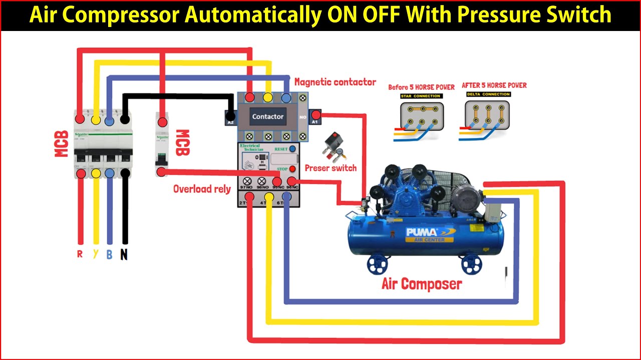
Decoding the Wiring Diagram: Symbols and Conventions
The wiring diagram is your roadmap. Understanding the symbols and conventions is essential. Common elements you'll encounter include:
- Lines: Represent wires. Solid lines indicate a direct connection. Dashed lines may indicate connections on a different plane or within a component.
- Colors: Wires are color-coded for easy identification:
- Black: Typically represents the "hot" or live wire (L1).
- White: Typically represents the neutral wire.
- Green (or Bare Copper): Represents the ground wire.
- Symbols for Components: Standardized symbols represent each component:
- Pressure Switch: Often shown as a switch with a circle connected to a pressure source.
- Motor: Typically represented as a circle with an "M" inside.
- Power Source: Shown as a sine wave or a representation of a wall outlet.
- Unloader Valve: A solenoid valve symbol connected to the pressure switch.
Keep in mind that diagrams may vary slightly, but the fundamental symbols and color coding remain consistent.
How It Works: The Electrical Flow
The basic operation is as follows:
- When the tank pressure drops below the cut-in pressure, the pressure switch closes its contacts.
- This completes the electrical circuit to the motor.
- The motor starts, driving the compressor pump and filling the tank with air.
- As the tank pressure rises, it eventually reaches the cut-out pressure.
- At this point, the pressure switch opens its contacts, breaking the circuit to the motor.
- The motor shuts off.
- The unloader valve, often controlled directly by the pressure switch, vents pressure from the pump head, making the next start easier.
- This cycle repeats automatically, maintaining the desired air pressure in the tank.
Real-World Use: Basic Troubleshooting Tips
Here are some common issues and how to troubleshoot them using your understanding of the wiring diagram:
- Motor Won't Start:
- Check the Power Source: Ensure the compressor is plugged in and the circuit breaker hasn't tripped.
- Inspect the Pressure Switch: Use a multimeter to check for continuity across the pressure switch contacts when the tank pressure is below the cut-in pressure. If there's no continuity, the switch is likely faulty.
- Examine the Motor: Check for a tripped thermal overload switch on the motor. If the motor is humming but not turning, it may be seized.
- Check wiring: Make sure wiring is intact, and connectors are secured.
- Motor Runs Continuously:
- Check for Leaks: A leak in the tank or air lines can cause the compressor to run continuously.
- Inspect the Pressure Switch: If the pressure switch contacts are stuck in the closed position, the motor will run continuously. Use a multimeter to confirm.
- Compressor Over-Pressurizes:
- Faulty Pressure Switch: If the pressure switch doesn't open at the cut-out pressure, the tank can over-pressurize, which is dangerous. Replace the pressure switch immediately.
Always disconnect the compressor from the power source before performing any troubleshooting or repairs.
Safety First: Risky Components and Precautions
Working with electrical components is inherently dangerous. Here's what to keep in mind:
- High Voltage: Air compressors operate on 120V or 240V AC, which can be lethal. Always disconnect the power before working on any electrical components.
- Capacitors: Some compressors use capacitors to help the motor start. These capacitors can store a dangerous electrical charge even after the compressor is unplugged. Discharge capacitors using a resistor before handling them. If you're not comfortable doing this, seek professional assistance.
- Pressure: Never attempt to repair a compressor while it's pressurized. Always release the pressure from the tank before working on it.
- Proper Grounding: Ensure the compressor is properly grounded to prevent electrical shocks.
- Use Proper Tools: Use insulated tools designed for electrical work.
If you are unsure about any aspect of the wiring or repair process, consult a qualified electrician. It's always better to be safe than sorry.
Conclusion
Understanding the air compressor pressure switch wiring diagram is a valuable skill for any DIY mechanic. By knowing the components, symbols, and operation, you can effectively diagnose and repair common compressor problems. Remember to prioritize safety and consult a professional when needed. With the knowledge you've gained, you're well-equipped to tackle your next compressor project confidently.
And as promised, we have the wiring diagram file ready for you. You can download it using this link: [Placeholder for Download Link]. Feel free to reference it as you work on your compressor!