
Air Conditioner Ac Compressor Diagram
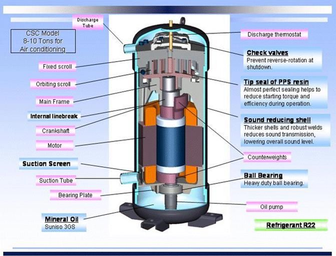
Understanding your car's air conditioning system is crucial for maintaining comfort and preventing costly repairs. A key element of this system is the AC compressor, and a detailed diagram is invaluable for diagnostics, repairs, and even upgrades. Think of the AC compressor diagram as the system's roadmap, guiding you through its complex network of hoses, valves, and components. This article will delve into the specifics of AC compressor diagrams, empowering you with the knowledge to tackle AC issues with confidence.
Why a Compressor Diagram Matters
The AC compressor diagram isn't just a pretty picture; it's a powerful tool for several reasons:
- Diagnosis: The diagram helps trace the flow of refrigerant, pinpointing potential leaks, blockages, or component failures. By understanding the system's layout, you can systematically isolate problems.
- Repair: Whether replacing a faulty compressor, condenser, or hose, the diagram ensures you're connecting components correctly and avoiding potential damage. It shows the precise routing of lines and the location of critical sensors.
- Learning: Studying the diagram provides a deeper understanding of the entire AC system, allowing you to grasp the relationship between different components and their functions.
- Modifications/Upgrades: If you're considering upgrading your AC system for better performance, the diagram will help you plan the installation of new components and ensure compatibility.
- Safety: Knowing the location of high-pressure lines and components is crucial for avoiding injury during repairs. The diagram can highlight potentially hazardous areas.
Key Specs and Main Parts Illustrated in a Diagram
An AC compressor diagram typically includes the following key specifications and main parts. Remember that diagrams can vary slightly depending on the vehicle make and model.
Main Components:
- Compressor: The heart of the system, responsible for compressing the refrigerant. Look for specifications like displacement (cc or cubic inches), type (e.g., scroll, reciprocating), and manufacturer part number.
- Condenser: Located in front of the radiator, the condenser dissipates heat from the high-pressure refrigerant vapor, turning it into a liquid.
- Evaporator: Located inside the dashboard, the evaporator absorbs heat from the cabin air, cooling it down.
- Expansion Valve/Orifice Tube: Controls the flow of refrigerant into the evaporator, causing a pressure drop and further cooling.
- Receiver Drier/Accumulator: Filters moisture and debris from the refrigerant, protecting the compressor. The receiver drier is typically used with expansion valve systems, while the accumulator is used with orifice tube systems.
- Refrigerant Lines (Hoses and Pipes): Connect all the components, carrying the refrigerant throughout the system. High-pressure and low-pressure lines are usually distinguished.
- Pressure Switches: Monitor the refrigerant pressure and protect the system from over-pressurization or under-pressurization.
- Sensors: Temperature sensors, pressure transducers, and other sensors provide feedback to the vehicle's control system.
Key Specifications:
Refrigerant Type: Often R-134a or the newer R-1234yf. The diagram will clearly indicate which refrigerant is compatible with the system. Using the wrong refrigerant can damage the system and is illegal.
Refrigerant Charge: The amount of refrigerant the system should hold, typically measured in ounces or grams. This is crucial for optimal performance.
Operating Pressures: The expected high-side and low-side pressures under various operating conditions (e.g., idle, high speed, ambient temperature). These values are essential for diagnosing performance issues.
Understanding Symbols, Lines, Colors, and Icons
AC compressor diagrams use a standardized set of symbols, lines, and colors to represent different components and flow paths. Familiarizing yourself with these conventions is essential for interpreting the diagram correctly.
- Solid Lines: Represent refrigerant lines (hoses or pipes). A thicker line might indicate a high-pressure line.
- Dashed Lines: Often represent electrical wiring or vacuum lines.
- Arrows: Indicate the direction of refrigerant flow.
- Colors: Different colors might be used to distinguish between high-pressure and low-pressure lines (e.g., red for high pressure, blue for low pressure). However, color coding isn't always consistent, so refer to the diagram's legend.
- Icons: Standardized icons represent components like the compressor (often a stylized pump), condenser (a serpentine coil), evaporator (another coil, often with fins), expansion valve (a variable restriction), receiver drier/accumulator (a cylindrical tank), and pressure switches (a switch symbol).
Example Icons: Look for symbols that resemble the actual components. A compressor might be a circle with a fan inside, while a condenser or evaporator would be a squiggly line indicating coil.
How It Works: The Refrigerant Cycle
The AC compressor diagram helps visualize the refrigerant cycle, which is the fundamental principle behind how air conditioning works:
- Compression: The compressor increases the pressure and temperature of the refrigerant vapor.
- Condensation: The high-pressure, hot refrigerant vapor flows to the condenser, where it releases heat and turns into a high-pressure, warm liquid.
- Expansion: The high-pressure liquid refrigerant flows through the expansion valve or orifice tube, where its pressure and temperature drop significantly.
- Evaporation: The low-pressure, cold refrigerant flows into the evaporator, where it absorbs heat from the cabin air, turning back into a low-pressure vapor.
- Return: The low-pressure refrigerant vapor returns to the compressor, completing the cycle.
The diagram shows the path of the refrigerant through each of these stages, highlighting the role of each component.
Real-World Use: Basic Troubleshooting Tips
With an AC compressor diagram, you can perform basic troubleshooting:
- Locating Leaks: Use the diagram to identify potential leak points (e.g., connections, seals). Use a UV dye and UV light to visually inspect for leaks.
- Identifying Blockages: Follow the refrigerant flow path on the diagram. If a component is excessively hot or cold, it might indicate a blockage.
- Checking Pressure Switches: The diagram shows the location of pressure switches. Use a multimeter to test their continuity and ensure they're functioning correctly.
- Verifying Component Function: Use the diagram to trace wiring and vacuum lines to components. Verify that they are receiving power or vacuum as required.
Important Note: Many AC repairs require specialized tools and knowledge. If you're not comfortable working with refrigerant, it's best to consult a qualified AC technician.
Safety Precautions
Working with AC systems can be dangerous:
- Refrigerant: Refrigerant can cause frostbite and asphyxiation. Always wear gloves and eye protection when working with refrigerant lines. Never release refrigerant into the atmosphere.
- High Pressure: AC systems operate at high pressures. Loosening connections without properly discharging the system can result in serious injury.
- Electrical Components: Disconnect the battery before working on any electrical components in the AC system.
Always consult your vehicle's service manual for specific safety instructions.
We have the AC compressor diagram file available. Please provide your vehicle's make, model, and year, and we will try to locate the appropriate diagram for you. Understanding and using this diagram will greatly enhance your ability to maintain and repair your vehicle's air conditioning system.