
Air Conditioner Compressor Parts Diagram
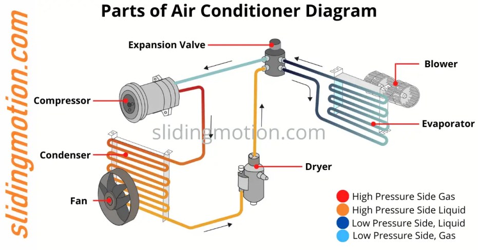
So, you're diving into the world of automotive air conditioning – specifically, the compressor. Good on you! Understanding this vital component is key to keeping your cool (pun intended!) and tackling potential A/C issues on your own. This article breaks down the air conditioner compressor parts diagram, explaining what each part does, how it all works together, and how to use the diagram for troubleshooting. Why bother? Well, knowing your way around the compressor can save you serious money on repairs, help you understand how to improve your A/C's performance, or simply satisfy your inner gearhead. Plus, we have the compressor parts diagram file for you to download after reading this article!
Purpose of the Compressor Parts Diagram
The compressor parts diagram is your roadmap to understanding the internal workings of your A/C compressor. It's more than just a pretty picture; it's a vital tool for:
- Diagnosis: Identifying faulty components based on symptoms.
- Repair: Understanding the assembly and disassembly process for repairs.
- Parts Identification: Accurately ordering the correct replacement parts.
- System Understanding: Grasping the flow of refrigerant and the function of each component within the compressor.
- Performance Tuning: While limited in scope, understanding the compressor can provide insights when trying to optimize your A/C system's cooling capacity.
Key Specs and Main Parts of an A/C Compressor
Before we dive into the diagram, let's cover some essential components and their specifications. Remember, specific specs will vary based on your vehicle's make and model, but the underlying principles remain the same.
Main Parts:
- Compressor Body: The main housing, usually made of cast aluminum, containing all the internal components.
- Clutch: An electromagnetic clutch that engages and disengages the compressor from the engine's drive belt. This is crucial for controlling when the A/C is actively cooling.
- Pulley: Driven by the engine's serpentine belt, the pulley provides the rotational force for the compressor.
- Input/Output Ports (Suction & Discharge): These ports connect the compressor to the rest of the A/C system. The suction port is where low-pressure refrigerant enters, and the discharge port is where high-pressure refrigerant exits.
- Piston(s)/Scroll: Depending on the compressor type (piston or scroll), this is the mechanism that actually compresses the refrigerant.
- Crankshaft/Swashplate: In piston compressors, the crankshaft (or swashplate) converts the rotational motion of the pulley into reciprocating motion of the pistons.
- Reed Valves/Check Valves: These one-way valves control the flow of refrigerant in and out of the cylinders (in piston compressors) or scroll chambers (in scroll compressors).
- Seals: Prevent refrigerant leaks, especially at the shaft where the pulley connects to the compressor.
- Oil Sump: Holds the refrigerant oil that lubricates the internal components.
- Pressure Relief Valve: A safety device that releases refrigerant if the pressure becomes excessively high, preventing damage to the compressor and system.
Key Specs: While the diagram primarily shows parts, some key specs to be aware of include:
- Refrigerant Type: R134a or R1234yf are common. Never mix refrigerants. Check your vehicle's specifications.
- Oil Type and Capacity: The correct oil type and amount are critical for lubrication and compressor longevity. PAG oils are commonly used.
- Displacement (cc/rev or in³/rev): This indicates the volume of refrigerant the compressor can pump per revolution.
- Maximum Operating Pressure: The maximum pressure the compressor is designed to handle.
Symbols: Decoding the Diagram
Understanding the symbols on the diagram is key to interpreting it correctly. Here's a breakdown of common symbols:
- Lines:
- Solid Lines: Usually represent physical connections or refrigerant flow paths.
- Dashed Lines: May indicate electrical connections or secondary paths.
- Arrowheads: Indicate the direction of refrigerant flow.
- Colors: While not standardized, colors can be used to differentiate components or systems. For example:
- Blue: Often indicates low-pressure side.
- Red: Often indicates high-pressure side.
- Icons:
- Circles: Can represent valves, pistons, or other cylindrical components.
- Squares/Rectangles: Often represent electrical components like the clutch coil.
- Zigzag Lines: Can represent electrical connections or windings.
- Abbreviations: Common abbreviations include:
- IN: Input
- OUT: Output
- LP: Low Pressure
- HP: High Pressure
- CL: Clutch
The diagram may also include exploded views to show the order of assembly and disassembly. Pay close attention to the orientation of parts.
How It Works: The Compression Cycle
The compressor is the heart of the A/C system, responsible for circulating and compressing the refrigerant. Here's a simplified overview of the compression cycle, specifically talking about a piston-style compressor:
- Intake (Suction): The piston moves down in the cylinder, creating a vacuum. This draws low-pressure, low-temperature refrigerant vapor from the evaporator (via the suction port) into the cylinder through the open reed valve.
- Compression: The piston moves up in the cylinder, compressing the refrigerant vapor. As the pressure increases, so does the temperature.
- Discharge: Once the pressure reaches a certain level, it overcomes the spring tension on the discharge reed valve, forcing it open. The high-pressure, high-temperature refrigerant vapor is then expelled from the cylinder through the discharge port.
- Repeat: This cycle repeats continuously as long as the compressor is engaged, circulating refrigerant through the entire A/C system.
Scroll compressors works slightly different, they use two interleaved spiral scrolls to compress the refrigerant.
Real-World Use: Basic Troubleshooting Tips
Now, let's put this knowledge into practice. Here are some basic troubleshooting tips using the compressor diagram:
- No A/C, Clutch Not Engaging: Check the electrical connections to the clutch coil. Use the diagram to locate the coil and trace the wiring back to the control system. A multimeter can help you test for voltage and continuity. Could be a bad clutch relay or a faulty pressure switch.
- No A/C, Clutch Engaging, No Cold Air: This could be due to low refrigerant, a faulty expansion valve, or a problem within the compressor itself. Listen for unusual noises from the compressor. A seized compressor (no rotation) is a serious issue.
- Loud Compressor Noise: Indicates potential internal damage. Consult the diagram to identify potentially worn or broken components like pistons, valves, or bearings. Consider replacing the entire compressor.
- Refrigerant Leak: Look for signs of oil residue around the compressor seals, especially the shaft seal. The diagram will help you identify the location of these seals.
- High Pressure Reading on Gauge: Could be a blocked condenser, overcharge refrigerant, or compressor malfunction. Consult the diagram to ensure proper operation of the pressure relief valve.
Disclaimer: These are just basic troubleshooting tips. Always consult a qualified technician for complex issues.
Safety First!
Working with A/C systems involves potential hazards. Here's what to keep in mind:
- Refrigerant: Refrigerant can cause frostbite and is harmful to the environment. Never release refrigerant into the atmosphere. Always recover it properly.
- High Pressure: The A/C system operates at high pressures. Incorrectly disconnecting lines can result in injury.
- Electrical: The clutch operates on electrical power. Disconnect the battery before working on electrical components.
- Moving Parts: Keep hands and tools clear of the pulley and belt when the engine is running.
- Proper Tools: Always use the correct tools for the job. This includes manifold gauges, vacuum pumps, and refrigerant recovery equipment.
Warning: The refrigerant circuit contains high-pressure refrigerant. Incorrectly servicing this system can result in personal injury or equipment damage. This article is for informational purposes only and does not constitute professional advice.
By understanding the A/C compressor parts diagram and how the compressor functions, you can confidently diagnose issues, perform basic repairs, and better understand your vehicle's air conditioning system. It's a valuable skill for any DIY mechanic or car enthusiast. Good luck, and stay cool!
Remember, we have that compressor parts diagram file ready for you. You can download it using the link provided below (link placeholder, will be functional when implemented).