
Air Conditioner Fan Motor Wiring Diagram
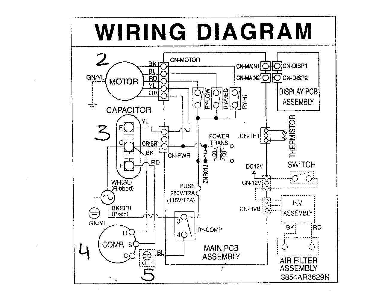
Let's dive into the often-overlooked, yet critically important, world of air conditioner fan motor wiring diagrams. If you're an experienced DIYer, a budding modder, or a car owner who likes to understand the inner workings of your vehicle, understanding these diagrams is a powerful tool. It allows you to diagnose issues, perform repairs, and even upgrade your cooling system with confidence. This article will break down the complexities of these diagrams, making them accessible and practical for your projects.
Purpose: Why Bother with Wiring Diagrams?
Why should you bother learning to read an AC fan motor wiring diagram? Several reasons:
- Diagnostics and Repair: When your AC fan motor isn't working, a wiring diagram is your roadmap to troubleshooting. It shows you exactly where to check for voltage, grounds, and broken connections. Without it, you're just guessing.
- Upgrades and Modifications: Planning to install a more powerful fan motor or add a relay for better control? A diagram ensures you wire everything correctly, preventing damage and ensuring optimal performance.
- Understanding Your System: Even if you don't plan on doing any repairs, understanding the diagram helps you grasp how your AC system functions as a whole. It's like having a blueprint to your car's cooling infrastructure.
- Avoiding Costly Mistakes: Incorrect wiring can damage components and even create dangerous electrical hazards. A wiring diagram helps you avoid these potentially expensive and dangerous mistakes.
Key Specs and Main Parts: What You Need to Know
Before we delve into the symbols and how the circuit works, let's review the key components and specifications you'll typically encounter in an AC fan motor wiring diagram:
- Fan Motor: The heart of the system, responsible for drawing air across the condenser or evaporator coil. These motors are typically 12V DC in automotive applications.
- Relay: An electromagnetic switch that allows a low-current circuit to control a high-current circuit (the fan motor). This protects the control circuit from overload.
- Fuse: A safety device designed to protect the circuit from overcurrent. If the current exceeds a certain level, the fuse blows, breaking the circuit.
- Resistor (Optional): Some systems use resistors to provide different fan speeds. By changing the resistance in the circuit, you reduce the voltage supplied to the motor, thus reducing its speed.
- Control Switch/Module: This can be a simple switch on the dashboard or a more sophisticated electronic control module (ECU) that controls the fan based on temperature sensors.
- Wiring: The conductors that carry electricity between the components. Wire gauge (thickness) is crucial; using the wrong gauge can lead to overheating and fire.
- Ground Connection: A crucial connection that provides a return path for the electricity. A poor ground connection can cause all sorts of problems.
Decoding the Diagram: Symbols, Lines, and Colors
Wiring diagrams use a standardized set of symbols to represent different components. Here's a breakdown of common symbols you'll find in an AC fan motor wiring diagram:
- Straight Lines: Represent wires. Thicker lines often indicate wires carrying higher current.
- Dotted Lines: May indicate shielded wires or wires that are part of a harness but not directly connected to the component in question.
- Circles with a "M" inside: Represent the fan motor.
- Rectangles: Often represent relays, switches, or control modules.
- Zigzag Lines: Represent resistors.
- Fuses: Depicted as a line with a "S" shape through it, or a rectangle with a diagonal line.
- Ground Symbol: Resembles an upside-down tree or a series of horizontal lines decreasing in length.
Color Coding: Color coding is essential for identifying wires. While standards exist, the specific colors used can vary between manufacturers and even between models of the same car. However, here are some common conventions:
- Red: Typically indicates a power wire connected directly to the battery.
- Black: Almost always indicates a ground wire.
- Other Colors: Indicate various signal and control wires. The diagram should include a color key to decode the function of each wire color.
How It Works: Tracing the Circuit
Let's understand how a typical AC fan motor circuit works. The diagram will show a simplified view of the following:
- Power Source: Power from the battery flows through a fuse to protect the circuit.
- Control Switch/Module: The switch (or the ECU) controls whether the circuit is active. When you turn on the AC, the switch closes, allowing current to flow to the relay.
- Relay Activation: The current from the switch energizes the relay coil, causing the relay's internal contacts to close.
- Power to the Motor: When the relay contacts close, power is supplied to the fan motor.
- Motor Operation: The fan motor spins, drawing air across the AC condenser or evaporator.
- Ground Return: The electricity flows through the motor and returns to the battery via a ground connection.
Some systems use a resistor in series with the motor to provide multiple fan speeds. When the switch is in a low-speed position, the current flows through the resistor, reducing the voltage to the motor and thus reducing its speed. In a high-speed position, the switch bypasses the resistor, allowing full voltage to the motor.
Real-World Use: Basic Troubleshooting
Armed with your understanding of the wiring diagram, you can begin basic troubleshooting when your AC fan motor malfunctions. Here are some common issues and how to diagnose them using the diagram:
- Fan Not Working at All:
- Check the Fuse: Use a multimeter to verify continuity across the fuse. If the fuse is blown, replace it with one of the same amperage rating.
- Check the Relay: You can test the relay by applying 12V to the relay coil (as indicated in the diagram). You should hear a click. Use a multimeter to check continuity across the relay contacts when the coil is energized.
- Check Voltage at the Motor: Use a multimeter to measure the voltage at the fan motor connector with the AC turned on. If you have 12V (or close to it), the motor itself is likely faulty.
- Check Ground Connection: Make sure the ground connection for the motor and the relay is clean and secure. A poor ground can cause intermittent or complete failure.
- Fan Only Works on High Speed: This often indicates a problem with the resistor(s) used for lower speeds. Use a multimeter to check the resistance of the resistor. If it's open (infinite resistance), the resistor is faulty.
- Intermittent Operation: This can be caused by loose connections, corroded terminals, or a failing relay. Inspect all connections carefully and clean any corrosion.
Safety First: Handling Electrical Components
Working with electrical components can be dangerous. Always follow these safety precautions:
- Disconnect the Battery: Before working on any electrical system, disconnect the negative battery cable to prevent accidental shorts.
- Use Proper Tools: Use insulated tools to avoid shocks.
- Work in a Well-Lit Area: Good visibility is essential for avoiding mistakes.
- Be Aware of Capacitors: Some circuits, especially those involving control modules, may contain capacitors that can store a charge even after the battery is disconnected. Discharge capacitors before working on the circuit. This is especially important!
- Never Work on a Live Circuit: Unless absolutely necessary for testing, always disconnect the battery before working on any wiring.
High-current components like the fan motor and the relay can generate significant heat and sparks if shorted. Always handle these components with care and ensure they are properly insulated.
Understanding your AC fan motor wiring diagram empowers you to diagnose problems, perform repairs, and even customize your car's cooling system. By familiarizing yourself with the symbols, components, and circuit operation, you can confidently tackle a wide range of automotive electrical projects.
Remember, while this article provides a general overview, specific wiring diagrams can vary significantly between makes and models. We have a collection of these diagrams available, and you can download the appropriate diagram here. Having the correct diagram is crucial for accurate troubleshooting and repair.