Air Conditioner Hard Start Kit Wiring Diagram
Air conditioner hard start kits can be a lifesaver for older AC units, particularly those that struggle to kick on, especially during peak summer heat. Understanding the wiring diagram for these kits is crucial for proper installation, troubleshooting, and even just understanding the inner workings of your AC system. This article will walk you through the key components, symbols, and procedures, empowering you to confidently work with these systems. We'll cover safety, troubleshooting, and offer a downloadable wiring diagram at the end for easy reference. Consider this your comprehensive guide to AC hard start kit wiring.
Why Understanding the Wiring Diagram Matters
Let's be clear: electricity and air conditioning systems are nothing to take lightly. But for the experienced DIYer, knowledge is power. The ability to decipher a hard start kit wiring diagram opens several doors:
- Repair and Troubleshooting: If your AC isn't starting, or you suspect a faulty hard start kit, the diagram helps you pinpoint the issue. You can trace wires, test components, and isolate the problem efficiently.
- Correct Installation: Improper wiring can damage your AC compressor, leading to costly repairs. The diagram ensures you connect everything correctly the first time.
- Understanding System Operation: Even if you're not actively working on your AC, understanding the wiring diagram gives you a deeper appreciation for how the system functions. This can be valuable for preventative maintenance and identifying potential problems before they become major issues.
- Modification and Upgrades: If you're considering adding other energy-saving components or modifications to your AC system, understanding the existing wiring is essential.
Having the ability to work safely and competently on your home’s cooling system is a great advantage. A solid understanding of the wiring will help you confidently make repairs or determine when you need to call the HVAC technician.
Key Specs and Main Parts of a Hard Start Kit
A hard start kit is designed to give your AC compressor an extra boost of power during startup. This is especially helpful for older units where the compressor motor windings may have slightly degraded over time.
The core components include:
- Start Capacitor: This is a high-capacitance capacitor (measured in microfarads, or µF) that temporarily stores energy and delivers a jolt of current to the start winding of the compressor motor. This provides the extra torque needed for startup. Values are typically specified within a range (e.g., 88-108 µF).
- Potential Relay (or Voltage Relay): This relay (electromechanical switch) senses the voltage across the start winding. When the compressor starts and the voltage rises, the relay opens, disconnecting the start capacitor from the circuit. This prevents the start capacitor from being continuously energized, which would damage it. It's rated for a specific voltage range.
- Run Capacitor (existing): While not *part* of the hard start kit, the hard start kit interfaces with the existing run capacitor circuit. The run capacitor is continuously energized during compressor operation, helping to improve efficiency. The total capacitance across the compressor should never exceed the manufacturers specifications.
- Wiring Harness: This includes the wires, connectors, and terminals needed to connect the kit components to the AC system. Color coding is crucial for proper connections.
Key Specifications to pay attention to include:
- Capacitance (µF) and Voltage (VAC) rating of the start capacitor: Ensure this matches the manufacturer's recommendations for your compressor.
- Voltage rating of the potential relay: Select a relay with a voltage rating appropriate for your AC system (usually 208-240 VAC).
- Compatibility: Not all hard start kits are compatible with all AC units. Check the manufacturer's specifications to ensure the kit is suitable for your system's voltage, compressor horsepower, and run capacitor value.
Understanding Wiring Diagram Symbols
Wiring diagrams use standardized symbols to represent electrical components and connections. Here's a breakdown of the most common symbols you'll encounter in a hard start kit diagram:
- Straight Lines: These represent wires. A solid line indicates a direct connection, while a dashed line might indicate a connection on another part of the diagram or a shielded cable.
- Dots: A dot where two or more lines intersect indicates an electrical connection. If lines cross without a dot, they are not connected.
- Capacitor Symbol: Typically two parallel lines, either straight or curved. A polarized capacitor (rare in hard start kits, but possible) will have a + sign next to one of the lines.
- Relay Symbol: A coil symbol represents the relay coil, which is energized to activate the relay. A switch symbol (a line that can move between two contacts) represents the relay contacts. You'll see Normally Open (NO) and Normally Closed (NC) contacts.
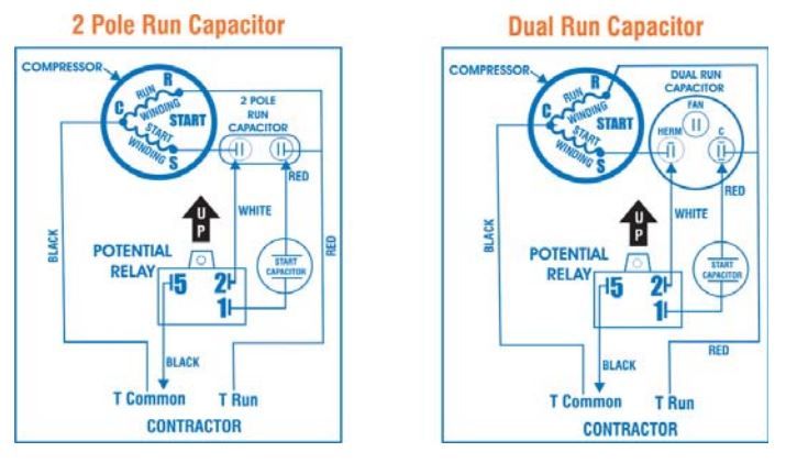
- Compressor Motor Windings: Often represented by circles with letter designations like "C" (Common), "S" (Start), and "R" (Run). These are the terminals on the compressor itself.
- Color Codes: Wires are often color-coded (e.g., Red, Black, White, Blue, Yellow) to help identify them. The wiring diagram should include a legend explaining the color codes.
Important Note: Different manufacturers might use slightly different variations of these symbols, so always refer to the specific wiring diagram that comes with your hard start kit. Never assume!
How a Hard Start Kit Works
The hard start kit enhances the startup torque of your AC compressor motor. Here's a step-by-step explanation:
- Startup: When the thermostat calls for cooling, power is supplied to the AC unit.
- Relay Activation: Initially, the potential relay is in its normally closed (NC) position. This allows current to flow through the start capacitor and into the start winding of the compressor motor.
- Boosting Torque: The start capacitor provides a significant surge of current to the start winding, creating a strong magnetic field that helps the rotor start turning. This overcomes the inertia and any resistance within the compressor.
- Relay Deactivation: As the compressor motor gains speed, the voltage across the start winding increases. When this voltage reaches a predetermined level, the potential relay coil energizes.
- Capacitor Disconnect: Energizing the relay coil causes the relay contacts to open, disconnecting the start capacitor from the circuit. The compressor continues to run using the run winding and the run capacitor.
- Normal Operation: The run capacitor remains in the circuit to improve the motor's efficiency and power factor during continuous operation.
In essence, the hard start kit provides a temporary "kick-start" to the compressor motor, making it easier to overcome the initial inertia and get up to speed. Without it, an aging compressor may draw excessive current trying to start, which can trip the breaker or damage the motor windings.
Real-World Use and Troubleshooting
Here are some practical scenarios and troubleshooting tips:
- AC Won't Start: First, check the breaker. If it's not tripped, inspect the wiring connections in the hard start kit. Ensure all connections are secure and free of corrosion. Use a multimeter to test for voltage at the compressor terminals. If voltage is present but the compressor isn't starting, the hard start kit or the compressor itself may be faulty.
- Clicking Sound, But No Start: This could indicate a faulty start capacitor or a stuck potential relay. Use a multimeter to test the capacitor for capacitance. If the reading is significantly lower than the rated value, the capacitor is likely bad. A persistent clicking from the relay may mean it's not properly switching.
- Compressor Starts, But Runs Roughly: This could indicate a problem with the run capacitor (part of the AC system, not the hard start kit itself), or even the compressor motor winding itself. Check the run capacitor's capacitance and look for signs of bulging or leaking.
- Hard Start Kit Fails Quickly: Repeated failure of the hard start kit often points to a more fundamental problem with the compressor, such as worn bearings or internal damage. Replacing the compressor may be the only long-term solution.
Before any testing, always disconnect power to the AC unit at the breaker!
Safety Considerations
Working with electricity is inherently dangerous. Here are some crucial safety precautions:
- Disconnect Power: Always disconnect power to the AC unit at the breaker before working on any electrical components. Verify the power is off using a non-contact voltage tester.
- Capacitor Discharge: Capacitors can store a dangerous charge even after the power is disconnected. Always discharge capacitors before handling them. Use a resistor (e.g., a 10,000-ohm, 2-watt resistor) to safely discharge the capacitor by connecting it across the terminals.
- Proper Tools: Use insulated tools designed for electrical work.
- Wear Safety Gear: Wear safety glasses and gloves.
- If Unsure, Consult a Professional: If you are not comfortable working with electricity, or if you encounter any unexpected problems, always consult a qualified HVAC technician. It's better to be safe than sorry.
- Beware of High Voltage: AC units typically operate at 220-240 volts, which is a potentially lethal voltage. Respect the dangers of electricity.
Ignoring these safety precautions can lead to serious injury or even death.
By understanding the purpose, components, and safety considerations of a hard start kit, you can confidently address common AC starting problems. Remember to always prioritize safety and consult a professional if you are unsure about any aspect of the repair.
You can download a comprehensive wiring diagram of a typical AC hard start kit here. This diagram will serve as a valuable reference for your future projects.