Air Horn Train Horn Wiring Diagram Without Relay
So, you're looking to wire up a train horn without a relay? That's a bold move! While relays offer added protection and can handle higher current loads, a direct wiring setup *can* be done, especially with smaller air horns or horns that draw less current. This article will guide you through creating a wiring diagram for a train horn system that omits the relay. This information is useful for understanding basic electrical principles, troubleshooting existing systems, or potentially building a simplified setup, though I strongly recommend considering a relay for most installations.
Why This Diagram Matters
Understanding this wiring diagram helps you in several ways:
- Repairing Existing Systems: If your horn system is malfunctioning, this diagram can help you trace wires and identify potential points of failure.
- Learning Electrical Fundamentals: Even if you ultimately choose to use a relay (which, again, is recommended), understanding a simpler, direct circuit will significantly improve your electrical knowledge.
- Simplified Setup (with caveats): For horns with *very* low current draw, this diagram allows for a cleaner, less complex installation. However, proceed with extreme caution and meticulous testing.
- Custom Modifications: Knowing the basic wiring allows you to incorporate other components, such as pressure gauges or solenoids, into your system more effectively.
Key Specs and Main Parts
Before diving into the diagram, let's outline the core components and their key specifications:
- Air Horn(s): These are your sound-producing devices. The most critical spec is the current draw (measured in amps) of the horn's solenoid. This will dictate the wire gauge you need. Look for this specification on the horn itself or its documentation.
- Air Compressor: Supplies the compressed air to the horn. The compressor needs a power source and a pressure switch.
- Air Tank: Stores the compressed air.
- Solenoid Valve: Electrically controlled valve that releases air to the horns when energized. Again, note the current draw. Some horns have integrated solenoids.
- Air Line: High-pressure hose connecting the air compressor, tank, and horn. Ensure it’s rated for the system's pressure.
- Fuse: A *critical* safety component. A fuse is a sacrificial device that breaks the circuit if the current exceeds a safe limit, preventing damage and potential fires. Its amperage rating should be slightly higher than the horn's maximum current draw.
- Switch: Activates the horn. Choose a switch rated for the current draw of the solenoid. A standard automotive toggle switch can often work, but verify its amperage rating.
- Wiring: Copper wire carrying the electrical current. The wire gauge (AWG - American Wire Gauge) must be thick enough to handle the current without overheating. Thicker wires have lower AWG numbers (e.g., 10 AWG is thicker than 16 AWG). A wiring gauge chart is essential.
- Grounding Wire: Connects the horn, compressor, and other components to the vehicle's chassis, providing a return path for the electrical current.
- Power Source: Typically the vehicle's 12V battery.
Symbols in the Diagram
Understanding the symbols is crucial for interpreting the wiring diagram. Here's a breakdown of common symbols:
- Solid Line: Represents a wire. The thicker the line, generally the higher the current capacity of the wire (though this isn't always a precise indicator).
- Dashed Line: Indicates a connection between components that isn't a direct electrical connection (e.g., an air line).
- Circle with a "+" inside: Positive (+) terminal of the battery.
- Circle with a "-" inside or three horizontal lines: Ground (-) or connection to the vehicle's chassis (ground).
- Rectangle with a zig-zag line inside: Resistor or, in this context, often represents the electrical coil within the solenoid.
- Fuse Symbol (various): Could be a small rectangle with a line through it, or a wavy line.
- Switch Symbol: A line that can be connected or disconnected, representing the switch's on/off state.
- Color Codes: Wires are often color-coded to aid identification. Common colors include:
- Red: Typically used for positive (+) wires.
- Black: Typically used for ground (-) wires.
- Blue, Yellow, Green: Used for various signal or power wires, depending on the specific application.
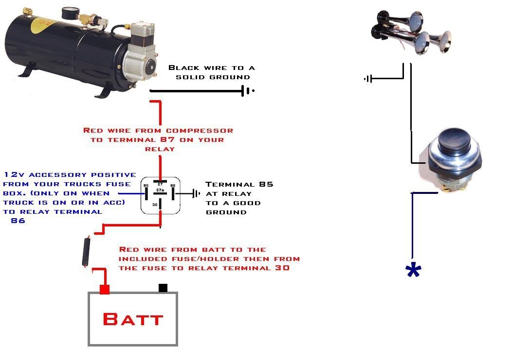
How It Works (Without a Relay)
Here's how the simplified circuit functions:
- Power Source: The circuit starts at the vehicle's 12V battery.
- Fuse: A fuse is connected in-line with the positive wire coming from the battery. This protects the entire circuit from overcurrent.
- Switch: From the fuse, the positive wire goes to the switch.
- Solenoid Valve: When the switch is closed (turned "on"), it completes the circuit, sending power to the solenoid valve.
- Air Release: The energized solenoid valve opens, allowing compressed air from the air tank to flow to the horn(s).
- Ground: The solenoid valve is connected to the vehicle's chassis (ground), completing the circuit.
- Horn Sounds: The pressurized air forces the horn(s) to produce a loud sound.
The Critical Caveat: This setup puts the full current draw of the solenoid directly through the switch. If the solenoid draws too much current, the switch can overheat, melt, and potentially cause a fire. This is why relays are strongly recommended. A relay uses a low-current circuit to control a high-current circuit.
Real-World Use: Basic Troubleshooting
If your horn isn't working, here's a basic troubleshooting approach:
- Check the Fuse: This is the first and most crucial step. A blown fuse is often the culprit. Replace it with a fuse of the *same* amperage rating. Never use a higher amperage fuse, as this defeats the purpose of the fuse and can lead to dangerous overheating.
- Test the Switch: Use a multimeter to check if the switch is working correctly. With the switch in the "on" position, the multimeter should show continuity (a closed circuit).
- Inspect Wiring: Look for any frayed wires, loose connections, or corrosion. Repair or replace damaged wiring.
- Verify Ground Connection: Ensure the ground connection is clean and secure. A poor ground connection can prevent the circuit from functioning correctly.
- Test the Solenoid Valve: You can test the solenoid valve by directly applying 12V to it. If it clicks, it's likely functioning. If it doesn't click, it might be faulty.
- Air Pressure Check: Make sure your air compressor is running and the air tank is pressurized. Use a pressure gauge to verify.
Safety Considerations
Working with electrical systems can be dangerous. Here are some crucial safety precautions:
- Disconnect the Battery: Always disconnect the negative terminal of the battery before working on any electrical components.
- Use Proper Tools: Use insulated tools to prevent electrical shock.
- Wear Safety Glasses: Protect your eyes from sparks and debris.
- Understand Wire Gauge: Choose the correct wire gauge for the current draw of the horn's solenoid. Undersized wires can overheat and cause a fire. Consult a wire gauge chart.
- Proper Fusing: *Always* use a fuse to protect the circuit. Ensure the fuse is properly sized for the application.
- Relays are Recommended: As stated repeatedly, a relay isolates the high-current horn circuit from the switch, providing a much safer and more reliable setup. Seriously consider using one.
- Professional Help: If you're unsure about any aspect of the wiring, consult a qualified electrician or automotive technician.
While this article provides a diagram for a direct-wired train horn system, I must reiterate the importance of using a relay. This simplified setup is primarily for educational purposes and should only be attempted with extreme caution and thorough testing. If you are committed to attempting this setup you will need to know the exact current draw of your horn and use a switch and wiring that is rated well above that draw.
We have a basic wiring diagram file available for download to registered users for convenience, as an example and starting point to help you visualize your design. Please remember safety and proper implementation are your responsibility.