Allen Bradley Wiring Diagrams Motor Starter
So, you're diving into the world of motor starters and Allen-Bradley wiring diagrams? Excellent! Whether you're looking to understand your car's electrical system better, planning a custom electrical modification, or just want to troubleshoot a starting issue, understanding these diagrams is crucial. We’re going to break down Allen-Bradley motor starter wiring diagrams in a way that makes sense, even if you're not an electrical engineer. Think of me as your friendly mechanic, translating the technical jargon into plain English.
Purpose of Allen-Bradley Motor Starter Wiring Diagrams
Why bother learning about these diagrams? Simple: they are the roadmaps to understanding, troubleshooting, and modifying motor starter circuits. Motor starters are essential components in many automotive applications, from starting electric fans to controlling auxiliary pumps. A clear wiring diagram lets you:
- Troubleshoot Issues: Pinpoint the exact location of a fault, whether it’s a blown fuse, a faulty relay, or a broken wire.
- Understand Operation: See the flow of electricity through the circuit, visualizing how each component interacts.
- Perform Repairs: Accurately replace faulty parts and rewire connections, ensuring everything works as intended.
- Design Modifications: Add new components, upgrade existing ones, or even design entirely new circuits with confidence.
- Safety: Work safely with electrical systems by understanding potential hazards.
Without a diagram, you're essentially working in the dark, relying on guesswork and potentially causing further damage or even injury. These diagrams are like having the schematics to your car's brain – vital for any serious DIYer.
Key Specs and Main Parts
Let's talk about the key players in a typical Allen-Bradley motor starter circuit. While specific components will vary depending on the application, here's a breakdown of the most common elements:
- Power Source: This provides the electrical energy to operate the circuit. In your car, this is typically the battery (12V DC).
- Overload Relay (OLR): This is a crucial safety device that protects the motor from overheating due to overcurrent. It monitors the current flowing to the motor and trips the circuit if it exceeds a safe threshold.
- Motor Starter Contactor: This is an electromagnetic switch that connects the power source to the motor. When energized, the contactor pulls in, completing the circuit and allowing current to flow to the motor.
- Motor: The device that converts electrical energy into mechanical energy (e.g., a radiator fan motor, a fuel pump motor).
- Control Circuit Transformer: In higher voltage systems (not typically in a car), a transformer steps down the voltage for the control circuit (e.g., from 120V AC to 24V AC) to improve safety and simplify control logic. This is rarely seen in automotive applications.
- Start/Stop Push Buttons: These are used to manually control the motor starter. The "Start" button momentarily closes a circuit to energize the contactor, while the "Stop" button opens the circuit to de-energize it.
- Auxiliary Contacts: These are additional contacts on the motor starter contactor that can be used for various purposes, such as interlocking circuits or providing status indication.
- Fuses/Circuit Breakers: Overcurrent protection devices that protect the circuit from short circuits and overloads.
Understanding Symbols in Allen-Bradley Wiring Diagrams
Wiring diagrams are written in a symbolic language. Once you learn the basics, it becomes relatively easy to decipher. Here are some common symbols you’ll encounter:
- Lines: Solid lines represent wires or conductors. Dashed lines often indicate mechanical linkages or connections between different parts of the diagram.
- Colors: Wire colors are often indicated in the diagram. Common colors include black (BLK), red (RED), white (WHT), blue (BLU), and green (GRN) for ground. Following color codes is essential for accurate wiring.
- Circles: Often represent components like pushbuttons or selector switches.
- Squares/Rectangles: Can represent various components like relays, contactors, or transformers. The specific symbol within the square/rectangle provides more detail.
- Coils: Represented by a circular or rectangular symbol with a winding pattern inside. These are used to represent the coils of relays or contactors.
- Contacts: Represented by a pair of lines. Normally open (NO) contacts are open when the coil is de-energized and closed when energized. Normally closed (NC) contacts are the opposite.
- Overload Relay Symbol: Typically a heater element symbol connected in series with the motor and a set of normally closed contacts.
It’s important to note that Allen-Bradley, while adhering to general electrical standards, might have slight variations in their specific symbol usage. Always refer to the specific Allen-Bradley documentation for the equipment you are working with.
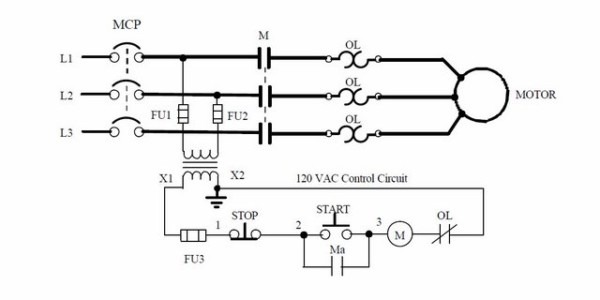
How It Works: A Simplified Explanation
Let's break down how a basic motor starter circuit works, focusing on a simple start/stop circuit.
- Power Up: The circuit is powered by a voltage source (e.g., 12V DC).
- Press "Start": When you press the "Start" button, you complete a circuit that energizes the motor starter contactor coil.
- Contactor Pulls In: The energized coil creates a magnetic field that pulls in the contactor. This closes the main contacts, connecting the power source to the motor.
- Motor Runs: The motor receives power and starts running.
- Holding Circuit: A "holding circuit," also known as a latching circuit, is created by using an auxiliary contact of the contactor in parallel with the "Start" button. This ensures that the contactor remains energized even after you release the "Start" button.
- Press "Stop": When you press the "Stop" button, you open the circuit to the contactor coil.
- Contactor Drops Out: The coil de-energizes, causing the contactor to drop out. This opens the main contacts, disconnecting the power source from the motor.
- Motor Stops: The motor stops running.
- Overload Protection: If the motor draws excessive current, the overload relay trips. This opens the normally closed contacts of the overload relay, which are in series with the contactor coil, de-energizing the contactor and stopping the motor.
Real-World Use: Basic Troubleshooting Tips
Okay, so your motor isn’t starting. What do you do? Here’s a basic troubleshooting approach using the wiring diagram:
- Check the Power Source: Is the battery charged? Are the fuses blown? Use a multimeter to verify voltage.
- Inspect the Wiring: Look for loose connections, frayed wires, or corrosion.
- Test the Start/Stop Buttons: Use a multimeter to check for continuity when the buttons are pressed and released.
- Check the Contactor: Is the contactor coil energized when the "Start" button is pressed? If not, check the wiring and the coil itself. Does the contactor *physically* pull in? If not, the contactor may be faulty.
- Inspect the Overload Relay: Has the overload relay tripped? If so, reset it. If it trips repeatedly, there's likely an overcurrent issue.
- Verify Motor Function: If all else fails, directly test the motor (if possible) to rule out a motor failure.
Important: Always disconnect the power source before working on electrical circuits to avoid electric shock.
Safety First! Highlighting Risky Components
Electrical circuits, especially those involving motors, can be dangerous. Here are some key safety considerations:
- High Voltage: Even 12V DC can deliver a nasty shock if you're not careful. Exercise caution and avoid touching exposed wires.
- Capacitors: Some circuits may contain capacitors that can store a charge even after the power is disconnected. Discharge capacitors before working on the circuit.
- Arc Flash: High-current circuits can produce an arc flash, which is an extremely dangerous explosion of electrical energy. Wear appropriate personal protective equipment (PPE) when working on high-current circuits.
- Lockout/Tagout: When working on electrical equipment, always use lockout/tagout procedures to ensure that the power cannot be accidentally turned on.
If you're not comfortable working with electrical circuits, consult a qualified electrician. It’s better to be safe than sorry.
Understanding Allen-Bradley motor starter wiring diagrams is a valuable skill for any DIY mechanic or car enthusiast. With a bit of practice and careful attention to detail, you can use these diagrams to troubleshoot problems, perform repairs, and even design custom electrical modifications. Remember to always prioritize safety and consult a qualified electrician if you're unsure about anything.
We have an example file of an Allen Bradley Wiring Diagram available for download. This diagram provides a practical example to supplement this discussion and help solidify your understanding.