Alpine Parking Brake Bypass Wiring Diagram
Let's dive into understanding the Alpine parking brake bypass wiring diagram. Whether you're installing a new Alpine head unit, troubleshooting an existing setup, or simply want a deeper understanding of how these systems interact, this knowledge is invaluable. This guide will walk you through the diagram, explain its components, and offer practical advice for real-world scenarios.
Purpose of the Parking Brake Bypass
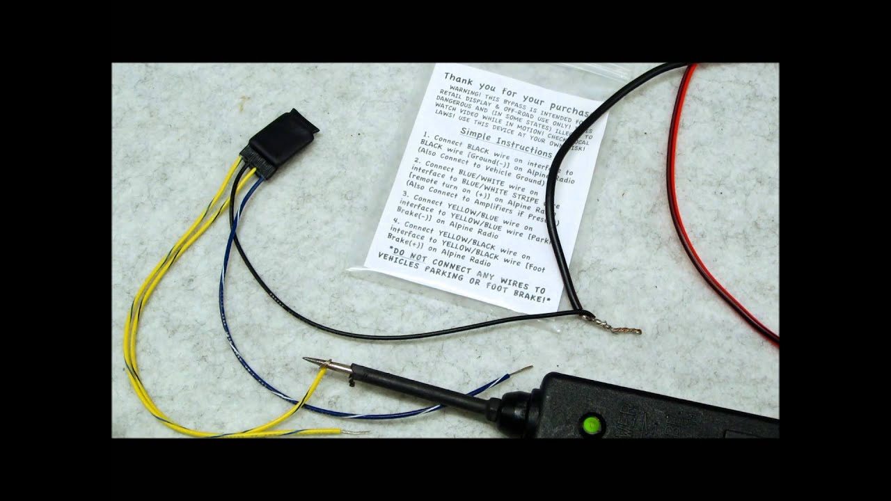
The parking brake bypass is a modification that circumvents the factory-installed safety feature preventing certain head unit functions (like video playback or advanced navigation setup) while the vehicle is in motion. Car manufacturers implement this as a safety measure to reduce driver distraction. However, many users find this restriction inconvenient, especially for passengers. The bypass allows these features to be accessed regardless of the parking brake status. Note: It is crucial to use this bypass responsibly and ensure that it does not contribute to distracted driving.
Key Specs and Main Parts of the Alpine Parking Brake System
The Alpine parking brake system, and therefore the bypass wiring, typically revolves around a few key components. Understanding their roles is essential for interpreting the wiring diagram:
- Head Unit: The central control and display unit. It's the brains of the operation and contains the software that enforces the parking brake lockout.
- Parking Brake Wire: A wire (usually light green or similar, but always refer to your specific Alpine model's documentation) that the head unit expects to be grounded when the parking brake is engaged.
- Ground Wire: A wire that provides a path to ground (the vehicle's chassis, typically). This is essential for completing the circuit and simulating the parking brake's engaged state.
- Relay (Optional but Recommended): A relay is an electrically operated switch. It allows you to isolate the parking brake wire signal. A relay provides a safer and more robust solution, especially if you plan on reverting back to the original parking brake functionality.
- Resistor (Sometimes Used): In some bypass methods, a resistor is used to simulate a specific voltage drop, mimicking the signal from the parking brake switch.
Key specs to consider include the voltage requirements (typically 12V DC) and the current draw of the head unit and any added components like relays. Always consult your Alpine head unit's manual for specific power and wiring requirements. Using the incorrect voltage can damage your head unit and potentially your car's electrical system.
Understanding the Symbols in the Wiring Diagram
Wiring diagrams use standardized symbols to represent components and connections. Here's a breakdown of common symbols:
- Solid Lines: Represent wires. The thickness of the line does not usually indicate the wire gauge, but it might in some diagrams for clarity.
- Dashed Lines: Often indicate shielded cables or connections that are not directly wired (e.g., communication signals).
- Circles with Numbers: Represent wire connections or termination points. The number usually corresponds to a connector pin or a wiring harness location.
- Ground Symbol (Usually three horizontal lines decreasing in size): Indicates a connection to the vehicle's chassis, providing a ground path.
- Battery Symbol: Represents the vehicle's battery and the source of power.
- Resistor Symbol (Zig-zag line): Indicates a resistor, which limits current flow.
- Relay Symbol: Shows a coil and switch contacts. The coil, when energized, closes or opens the switch contacts.
- Color Codes: Wires are often labeled with color codes (e.g., GRN for green, BLU for blue, RED for red). These codes help you identify the correct wires in the vehicle's wiring harness.
Color codes are *extremely* important. Do not assume wire colors are universal across all vehicles or even all Alpine models. Always verify the wire color and function with your specific model's wiring diagram before making any connections. Mistaking a wire's function can lead to serious electrical problems.
How the Parking Brake Bypass Works
The fundamental principle behind the bypass is to trick the head unit into thinking the parking brake is always engaged. The head unit checks the voltage level on the parking brake wire. When the parking brake is engaged, the switch connected to the parking brake wire closes, grounding the wire. This ground signal triggers the head unit to allow access to restricted features.
The bypass achieves this by permanently grounding the parking brake wire. This can be done in a few ways:
- Direct Grounding: Simply connecting the parking brake wire directly to a ground point. This is the simplest method but also the least flexible.
- Relay Method: Using a relay to switch the parking brake wire between the original parking brake switch and a ground. This allows you to easily revert to the original functionality. Typically, the relay coil is connected to a switched 12V source (meaning it's only powered when the ignition is on). When the relay is energized, it grounds the parking brake wire.
- Resistor Method: Using a resistor in series with a ground connection to simulate a specific voltage drop that mimics the parking brake signal. This method is less common but can be used in certain situations where the head unit requires a specific voltage level rather than a simple ground.
The relay method is the preferred approach because it allows for easily toggling the bypass functionality. You can wire a switch to the relay coil, allowing you to enable or disable the bypass as needed.
Real-World Use and Basic Troubleshooting Tips
Here are some troubleshooting tips when implementing or diagnosing a parking brake bypass:
- No Video Playback: If you've installed the bypass and video playback still doesn't work, double-check the grounding connection. Make sure it's a solid, clean ground. Also, verify that you've connected to the correct parking brake wire on the head unit.
- Head Unit Malfunctions: If the head unit behaves erratically after the bypass installation, check for short circuits or loose connections. A faulty ground can also cause unexpected behavior.
- Parking Brake Light Remains On: If you've used the relay method and the parking brake light on your dashboard stays on, the relay might be malfunctioning, or the wiring may be incorrect.
- Use a Multimeter: A multimeter is your best friend for troubleshooting electrical issues. Use it to check for continuity, voltage, and resistance to identify problems.
Remember to always disconnect the vehicle's battery before working on the electrical system. This will prevent accidental short circuits and potential damage to the vehicle or yourself.
Safety Considerations
Working with a car's electrical system involves inherent risks. Here are some critical safety points:
- Disconnect the Battery: Always disconnect the negative terminal of the battery before starting any electrical work.
- Use Proper Tools: Use insulated tools to prevent electrical shocks.
- Avoid Working in Wet Conditions: Water and electricity are a dangerous combination.
- Identify Wires Correctly: Use a wiring diagram and a multimeter to positively identify wires before making any connections.
- Protect Wiring: Use heat shrink tubing or electrical tape to insulate and protect connections.
- Fuses: Ensure any inline fuses are of the correct amperage rating for the circuit.
The most risky component in this modification is the constant power source. A poorly insulated or improperly connected wire to the car battery can lead to short circuits, fires, and damage to the car's electronic control units (ECUs). Therefore, you need to make sure any wire that taps the car battery for power has correct fuses and is properly insulated. Double-check all connections and insulation before turning the car's electrical system back on.
Modifying your vehicle's electrical system can void warranties or create safety hazards if done incorrectly. If you are not comfortable with electrical work, it is best to consult with a qualified professional.
We have the detailed Alpine parking brake bypass wiring diagram file available for download. This diagram will provide the specific pinouts and wire colors for your Alpine head unit model, making the installation process much smoother and safer. Please use it responsibly and always prioritize safety. Remember, driving safely is paramount. This bypass should only be used when it does not distract the driver.