Alternator External Voltage Regulator Wiring Diagram
So, you're diving into the fascinating world of alternator external voltage regulators! Whether you're troubleshooting a charging issue, upgrading your classic ride, or just want to understand how these systems tick, knowing your way around an external voltage regulator wiring diagram is essential. Think of it as the roadmap to your charging system's brain.
Purpose of Understanding the Diagram
Why bother with a diagram? Simple: it's your key to repairing, modifying, and understanding your vehicle's charging system. Without it, you're just guessing when diagnosing issues. A clear understanding allows you to:
- Diagnose Charging Problems: Is your battery not charging? The diagram helps pinpoint the faulty component (alternator, regulator, wiring).
- Perform Upgrades/Modifications: Swapping alternators? Upgrading to a higher amperage unit? You'll need to properly wire in the new regulator.
- Understand System Operation: Knowledge is power. Knowing how the system works allows for better preventive maintenance.
- Retrofit Systems: Many older vehicles used external regulators. Understanding the wiring allows you to maintain these systems or even update them with modern internal regulation.
Key Specs and Main Parts
Before we delve into the diagram, let's familiarize ourselves with the main players in an externally regulated charging system. These components work together to keep your battery charged and your electrical system humming. The *alternator* generates the AC current that the *rectifier* converts to DC.
- Alternator: The AC voltage generator. It's driven by the engine, typically via a belt. Key specs include amperage output (e.g., 60 amps, 100 amps, etc.) and voltage (typically 12V or 24V).
- External Voltage Regulator: The brain of the operation. It senses the battery voltage and controls the alternator's output to maintain a stable charging voltage. Different types exist, including electromechanical (relay-based) and solid-state. Specifications include the regulated voltage setpoint (e.g., 13.8V, 14.2V) and the current capacity.
- Battery: The energy storage device. Its voltage is what the regulator monitors.
- Wiring Harness: The network of wires connecting everything. Wire gauge (thickness) is critical for handling the current flow.
- Fuses/Fusible Links: Safety devices that protect the system from overcurrent.
Symbols – Decoding the Wiring Diagram
Understanding the symbols on the diagram is crucial for tracing circuits and identifying components. Here's a breakdown of common symbols:
- Solid Lines: Represent wires. The thickness of the line may (but doesn't always) indicate wire gauge.
- Dashed Lines: Often indicate ground connections or shielded cables.
- Circles: Represent connection points or terminals.
- Rectangles: Can represent various components, like the voltage regulator itself. Internal components within the regulator are often shown within this rectangle (resistors, transistors, relays).
- Zigzag Lines: Usually represent resistors.
- Alternator Symbol: Often looks like a circle with three diodes inside, representing the rectifier bridge.
- Battery Symbol: Parallel lines, one longer than the other, representing the positive and negative terminals.
- Ground Symbol: Usually a series of horizontal lines, decreasing in size.
- Color Coding: Extremely important! Most diagrams use standard automotive color codes (e.g., Red for battery positive, Black for ground, Yellow for ignition-switched power). Pay attention to the legend that tells you which color represents which signal.
Understanding Wire Colors
Automotive wiring uses a standard color code to help technicians identify wires and their functions. While this code isn't universal across all manufacturers and model years, some colors are very common. Here's a general guideline:
- Red: Typically used for battery positive (B+) or constant power.
- Black: Almost always represents ground.
- Yellow: Often used for circuits powered by the ignition switch when in the "run" or "accessory" position.
- Blue: Frequently used for lighting circuits.
- Green: Common for various signal circuits, like sensor outputs.
- White: Often used for circuits with a dedicated function or signal.
- Brown: Sometimes used for accessory circuits or courtesy lights.
Always check the specific wiring diagram for your vehicle to confirm the wire color codes.
How It Works – A Simplified Explanation
In a nutshell, the external voltage regulator monitors the battery voltage. If the voltage drops below a setpoint (e.g., 13.8V), the regulator increases the current flowing through the alternator's field winding (the rotor). Increasing the field current strengthens the magnetic field inside the alternator, which in turn increases the alternator's output voltage. Conversely, if the battery voltage exceeds the setpoint, the regulator reduces the field current, lowering the alternator's output. The regulator acts as a feedback loop, constantly adjusting the alternator's output to maintain a stable charging voltage.
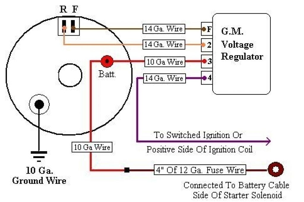
A typical external regulator will have several connections, often labeled something like:
- Battery (B or BAT): Connects directly to the battery positive terminal.
- Field (F): Connects to one of the field terminals on the alternator. This controls the amount of voltage the alternator generates.
- Ignition (I or IGN): Connects to a switched power source (ignition switch). This energizes the regulator when the engine is running.
- Ground (G or GND): Connects to a good chassis ground.
Think of it like this: the alternator is the engine, the voltage regulator is the throttle, and the battery voltage is the speedometer. The regulator keeps the "speed" (voltage) constant by adjusting the "throttle" (alternator output).
Real-World Use – Basic Troubleshooting Tips
Here are a few basic troubleshooting steps you can take using the wiring diagram:
- No Charging: Check the voltage at the alternator's output terminal (B+). If it's low (significantly below battery voltage when the engine is running), check the wiring connections to the voltage regulator and alternator field. Use a multimeter to verify that the ignition wire to the regulator has power when the ignition is on. Check the ground connection for corrosion.
- Overcharging: If the battery voltage is excessively high (e.g., above 15V), the regulator might be faulty. Check the regulator's ground connection. A bad ground can cause erratic readings. Replace the regulator if necessary.
- Intermittent Charging: Loose wiring connections are a common cause. Carefully inspect all connections for corrosion or looseness. Wiggle the wiring harness while monitoring the battery voltage to see if you can induce the problem.
Remember to use a multimeter to perform voltage and continuity tests. A test light can be useful for quick checks, but a multimeter provides more accurate readings.
Safety – Handle with Care!
Working with automotive electrical systems can be dangerous. Here are some safety precautions:
- Disconnect the Battery: Always disconnect the negative battery cable before working on the electrical system. This prevents short circuits and potential shocks.
- Be Careful Around Moving Parts: The alternator belt and pulley are rotating at high speed when the engine is running. Keep your hands and clothing away from these parts.
- Use Proper Tools: Use insulated tools to prevent short circuits.
- Work in a Well-Ventilated Area: Batteries can produce hydrogen gas, which is flammable.
- Fuses Are Your Friends: Never bypass a fuse or fusible link. They protect the system from overcurrent. If a fuse keeps blowing, find the short circuit that's causing it.
- Capacitors in the system may contain high voltage even after the car has been turned off. Do not touch the capacitor.
High voltage components in the charging system, particularly the alternator itself, can deliver a nasty shock. Exercise extreme caution!
Understanding your vehicle's charging system is a rewarding endeavor. With the help of the right wiring diagram and a little patience, you can diagnose and repair many common charging system problems. Good luck!
We have a detailed, downloadable diagram available. Contact us through the link below to request the file.