Alternator To Battery Wiring Diagram
Understanding the alternator-to-battery wiring diagram is fundamental for anyone tackling automotive electrical repairs, modifications, or even advanced diagnostics. This diagram isn't just a piece of paper; it's a roadmap to the heart of your vehicle's power system. Whether you're troubleshooting a charging issue, upgrading your electrical system for aftermarket accessories, or simply expanding your automotive knowledge, this guide will break down the diagram and equip you with the skills to interpret it.
Why This Diagram Matters
An alternator-to-battery wiring diagram is crucial for several reasons:
- Troubleshooting Charging Issues: Diagnosing why your battery isn't charging correctly is a primary use case. The diagram allows you to trace the circuit, identify potential breaks, shorts, or faulty components.
- Electrical System Upgrades: Adding high-power accessories like amplifiers, winches, or lighting requires understanding how the alternator and battery interact. This diagram helps you determine if your existing system can handle the increased load and where to properly connect the new components.
- Repairing Damaged Wiring: Accidents or wear and tear can damage wiring harnesses. The diagram is essential for correctly splicing or replacing damaged wires, ensuring proper functionality and preventing further issues.
- Understanding the Electrical System: Even if you're not actively working on your car, understanding the diagram gives you a deeper insight into how your vehicle's electrical system functions. This knowledge can be invaluable for preventative maintenance and identifying potential problems before they escalate.
- Ensuring Proper Grounding: A frequent cause of electrical malfunctions is poor or missing grounds. The diagram highlights grounding locations, which are critical for the return path of current and proper component operation.
Key Specs and Main Parts
Before diving into the diagram, it's essential to understand the main components involved in the alternator-to-battery charging circuit and their basic specifications.
- Alternator: The alternator is the heart of the charging system. It converts mechanical energy from the engine into electrical energy (AC, which is then rectified to DC) to charge the battery and power the vehicle's electrical loads. Alternator specifications include its output amperage rating (e.g., 90A, 120A, 150A), which indicates its maximum current output, and its voltage (typically 12V or 14V).
- Battery: The battery provides the initial power to start the engine and acts as a voltage stabilizer for the electrical system. Battery specifications include its cold cranking amps (CCA), which indicates its ability to start the engine in cold weather, and its amp-hour (Ah) rating, which indicates its storage capacity.
- Voltage Regulator: The voltage regulator controls the alternator's output voltage, preventing overcharging of the battery and protecting the electrical system from voltage spikes. In many modern vehicles, the voltage regulator is integrated within the alternator.
- Fusible Link/Fuse: A fusible link or a high-amperage fuse protects the wiring harness from excessive current flow in case of a short circuit. It's a crucial safety device. These are rated in Amps and Volts.
- Wiring Harness: The wiring harness consists of various wires that connect the alternator, battery, voltage regulator, and other components. Wire gauge (thickness) is important; thicker wires can handle higher current loads. Common wire gauges in this circuit include 4 AWG, 8 AWG, and 10 AWG.
- Ground Cables: Ground cables provide the return path for current to the battery's negative terminal. Ensure good contact to bare, clean metal.
Symbols – Understanding the Diagram's Language
Wiring diagrams use standardized symbols and conventions to represent electrical components and connections. Here's a breakdown of common symbols you'll encounter in an alternator-to-battery diagram:
- Solid Lines: Solid lines represent wires. The thickness of the line may (but doesn't always) indicate the wire gauge.
- Dashed Lines: Dashed lines often represent shielded wires or wires that are part of a larger harness.
- Color Codes: Wire colors are usually indicated by abbreviations (e.g., RED, BLU, GRN, BLK, YEL). Consult the diagram's legend to decipher the codes.
- Ground Symbol: The ground symbol (often a series of horizontal lines decreasing in length or a triangle pointing downwards) indicates a connection to the vehicle's chassis, providing a return path for current. Proper grounding is crucial!
- Battery Symbol: A series of long and short parallel lines. The longer line represents the positive terminal (+) and the shorter line the negative terminal (-).
- Alternator Symbol: Varies, but often a circle with internal windings represented. Specific connections (e.g., B+, Field, Stator) are usually labeled.
- Fuse Symbol: A wavy line within a rectangle or a simple rectangle with a line through it.
- Connector Symbols: Represented by various shapes, indicating a plug-in connection point. Connectors are often numbered or lettered for easy identification.
How It Works: The Charging Circuit Explained
The alternator-to-battery charging circuit works as follows:
- When the engine starts, the alternator begins to rotate, driven by the engine's belt system.
- The alternator generates AC voltage, which is then rectified (converted) to DC voltage by internal diodes.
- The voltage regulator monitors the battery's voltage and adjusts the alternator's output accordingly. If the battery is low, the regulator increases the alternator's output; if the battery is fully charged, the regulator reduces the output to prevent overcharging.
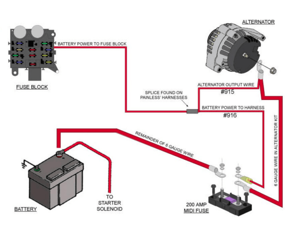
- The alternator's output (B+ terminal) is connected to the battery's positive terminal through a heavy-gauge wire, often protected by a fusible link or fuse. This wire carries the charging current to the battery.
- The battery provides power to the vehicle's electrical system, and the alternator replenishes the battery's charge.
- The alternator and battery are both connected to the vehicle's chassis through ground cables, providing a return path for current. A clean, solid ground connection is absolutely vital for proper operation.
Real-World Use: Basic Troubleshooting Tips
Here are some basic troubleshooting tips using the alternator-to-battery wiring diagram:
- Battery Not Charging:
- Check the fusible link or fuse between the alternator and battery.
- Use a multimeter to measure the voltage at the alternator's B+ terminal. It should be close to the battery voltage when the engine is off and higher (e.g., 13.5-14.5V) when the engine is running.
- Check the ground connections for corrosion or looseness.
- Test the alternator using a specialized alternator tester.
- Battery Overcharging:
- Suspect a faulty voltage regulator. If it's integrated into the alternator, the entire alternator may need to be replaced.
- Excessive Voltage Drop:
- Use a multimeter to measure the voltage drop across the charging circuit. A significant voltage drop indicates excessive resistance, possibly due to corroded connections or damaged wiring.
- Warning Light On:
- Often indicates a charging system issue. Use the diagram to check connections and voltages. Get the codes read by a scanner.
Safety – Proceed with Caution
Working with automotive electrical systems can be dangerous. Here are some important safety precautions:
- Disconnect the Battery: Always disconnect the battery's negative terminal before working on any electrical components. This prevents accidental short circuits.
- Avoid Contact with Live Wires: Never touch exposed wires or terminals while the engine is running or the battery is connected.
- Use Insulated Tools: Use tools with insulated handles to protect yourself from electric shock.
- Be Careful Around the Alternator: The alternator can get very hot during operation. Avoid touching it immediately after the engine has been running.
- The B+ terminal on the alternator carries full battery voltage and can deliver a significant current. Shorting it to ground can cause sparks, fires, and damage to the electrical system.
Remember, this guide provides a general overview. Consult your vehicle's specific wiring diagram for accurate information and component locations. Automotive electrical systems can be complex, so if you're not comfortable working with electricity, it's always best to consult a qualified mechanic.
We have a sample alternator-to-battery wiring diagram file that you can download to further your understanding. It provides a visual representation of the concepts discussed in this article and can be a valuable reference for your future projects. Contact us for the download link.