Alternator Voltage Regulator Wiring Diagram
So, you're diving into the electrical heart of your charging system – the alternator voltage regulator. Understanding its wiring is crucial, whether you're troubleshooting a dead battery, upgrading your alternator, or simply expanding your automotive knowledge. This guide will walk you through a typical alternator voltage regulator wiring diagram, explaining each component and its function. We'll break down the symbols, discuss how it all works, and even offer some real-world troubleshooting tips. And, heads up, we have a downloadable wiring diagram file ready for you at the end of this article.
Purpose of Understanding the Wiring Diagram
Why bother with a wiring diagram? Simple: It's your roadmap to a functional charging system. The alternator voltage regulator diagram becomes invaluable in these scenarios:
- Diagnosis and Repair: Pinpointing the source of charging system problems (e.g., overcharging, undercharging, no charging at all).
- Alternator Upgrades: Ensuring proper connections when installing a higher-output alternator or a different type of regulator.
- Custom Wiring: Modifying your vehicle's electrical system, for example, adding auxiliary batteries or implementing a standalone charging system.
- Learning and Education: Deepening your understanding of automotive electrical systems and how they interact.
Key Specs and Main Parts
Let's cover the vital components and their specifications, so you understand what we're looking at in the diagram.
Main Components:
- Alternator: The powerhouse responsible for generating electrical power to charge the battery and run electrical accessories. Key specs include its output amperage (e.g., 100A, 150A) and voltage (typically 12V or 14V).
- Voltage Regulator: The brain of the operation. It monitors the battery voltage and controls the alternator's output to maintain a stable charging voltage (usually around 14.4V). Different types exist:
- Internal Regulator: Integrated within the alternator itself.
- External Regulator: A separate module mounted externally. Older vehicles frequently use these.
- Battery: The energy storage device that provides power to start the engine and run electrical accessories when the alternator isn't producing sufficient power. Its voltage (12V) and Cold Cranking Amps (CCA) are essential specs.
- Ignition Switch: Controls the flow of power to various circuits, including the alternator's field circuit (which we'll discuss later).
- Fusible Links/Fuses: Overcurrent protection devices that prevent damage to the wiring and components in case of a short circuit.
Understanding Wiring Diagram Symbols
A wiring diagram speaks in symbols. Let's decipher them.
- Lines: Represent wires or conductors. The thickness of the line sometimes, but not always, indicates the wire gauge (thicker lines generally correspond to larger gauge wires).
- Colors: Wire colors are standardized in automotive wiring (though variations exist). Important: Never assume colors are consistent across all vehicles. Always verify with a diagram specific to your vehicle. Common colors include red (power), black (ground), and various other colors for signal and control wires.
- Circles: Represent connections or terminals.
- Rectangles: Typically represent components like relays, switches, or electronic modules.
- Ground Symbol ( ┴ ): Indicates a connection to the vehicle's chassis, providing a return path for the electrical current.
- Resistor Symbol ( ⎴ ): Represents a resistor, which limits the flow of current.
- Diode Symbol ( ◄| ): Represents a diode, which allows current to flow in only one direction. Often found in the alternator rectifier.
- Fuses: Represented by a looped line intersecting the main line.
How the Alternator Voltage Regulator System Works
The system's operation is a beautifully orchestrated dance of electricity and control.
- Ignition On: When you turn the ignition key, power is supplied to the voltage regulator.
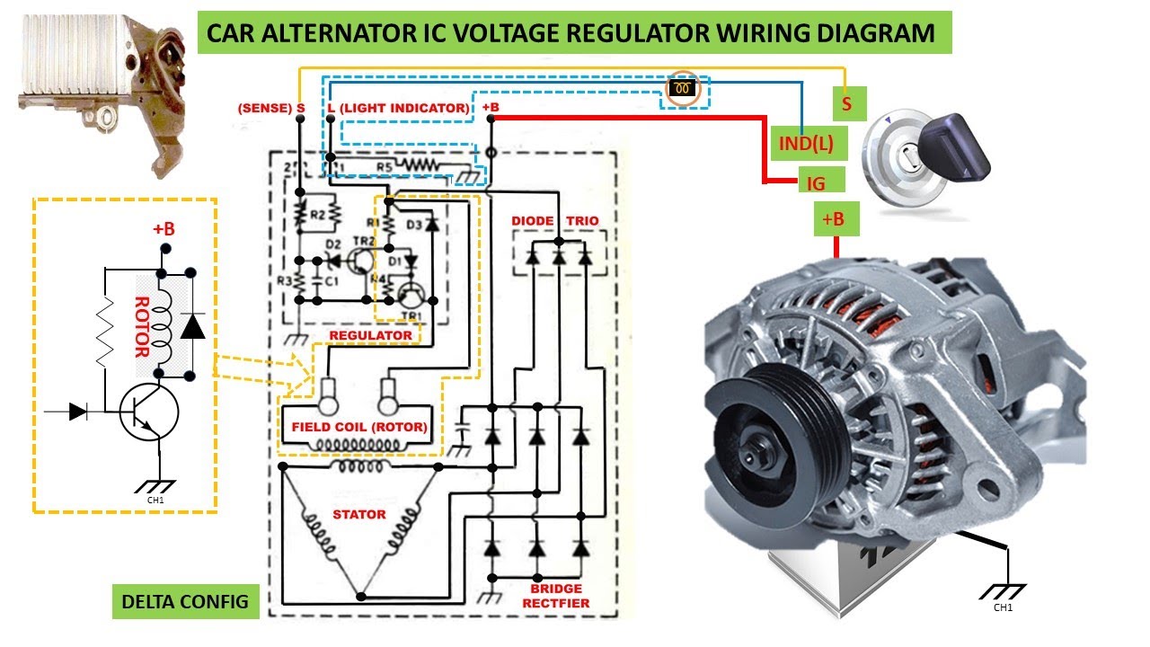
- Field Excitation: The regulator sends a small current to the alternator's field winding (also known as the rotor). This creates a magnetic field. The wire that carries this current is often labeled the "field wire," "exciter wire," or "IG" wire.
- Alternator Operation: As the engine spins, the alternator's rotor rotates within the stator windings. This rotating magnetic field induces a voltage in the stator windings, generating AC (alternating current) electricity.
- Rectification: The AC voltage is then converted to DC (direct current) voltage by a rectifier bridge (a set of diodes) inside the alternator.
- Voltage Regulation: The voltage regulator continuously monitors the battery voltage. If the battery voltage is low, the regulator increases the current flowing through the field winding, strengthening the magnetic field and increasing the alternator's output. Conversely, if the battery voltage is high, the regulator decreases the field current, reducing the alternator's output.
- Battery Charging and Accessory Power: The regulated DC voltage from the alternator charges the battery and provides power to run the vehicle's electrical accessories.
Real-World Use and Basic Troubleshooting Tips
Let's put this knowledge to practical use with some basic troubleshooting scenarios.
- Battery Not Charging:
- Check the alternator belt for proper tension.
- Inspect the battery terminals for corrosion and clean them if necessary.
- Use a multimeter to check the battery voltage with the engine running. It should be around 14.4V. A lower voltage indicates a potential charging problem.
- Check the alternator field wire for voltage with the ignition on. No voltage indicates a problem with the ignition switch or wiring.
- Check the continuity of the ground wires connecting the alternator to the chassis.
- Overcharging:
- Check the voltage regulator for proper operation. A faulty regulator can cause the alternator to overcharge the battery.
- Look for loose or corroded wiring that might be affecting the voltage regulator's readings.
- Warning Light On:
- A lit charging system warning light (often a battery symbol) indicates a problem with the charging system. Use a multimeter to check the charging voltage and diagnose the issue.
Safety Considerations
Working with electrical systems can be dangerous. Here's what to keep in mind:
- Battery Disconnect: Always disconnect the negative battery cable before working on the electrical system to prevent accidental short circuits.
- High Voltage: The alternator produces relatively high voltage and current. Avoid touching any exposed terminals while the engine is running.
- Proper Tools: Use insulated tools designed for electrical work.
- Fuses: Never bypass fuses or fusible links with wire or other conductive materials. This can create a fire hazard.
- Capacitors: Large capacitors (often used in audio systems) can store a dangerous electrical charge even after the power is disconnected. Discharge them properly before handling.
By understanding the alternator voltage regulator wiring diagram and its function, you'll be well-equipped to diagnose and repair charging system problems, upgrade your alternator, or simply gain a deeper understanding of your vehicle's electrical system. Remember to always consult your vehicle's specific wiring diagram for accurate information.
Ready to get your hands on a downloadable copy of a typical alternator voltage regulator wiring diagram? We have the file! It's a great resource to keep handy for future reference. Download the diagram HERE. (Link will lead to the download)