Alternator Wiring Diagram External Regulator
So, you're diving into the world of alternator wiring, specifically the type that uses an external regulator. Good on you! Understanding this system is crucial whether you're wrestling with a vintage restoration, diagnosing charging issues in an older vehicle, or even customizing a classic car. Many older vehicles, and some industrial and agricultural equipment, utilized this system for voltage regulation, and knowing how it all connects can save you a bundle in shop fees and prevent potentially damaging electrical problems.
Purpose of an External Regulator Wiring Diagram
Why bother with this diagram? Simply put, it's your roadmap to understanding, diagnosing, and repairing the charging system. Here's why it matters:
- Repair and Replacement: If your alternator isn't charging correctly, the diagram helps you trace wires, identify faults (like shorts or open circuits), and replace damaged components accurately.
- Modification and Upgrades: Thinking about swapping in a different alternator? The diagram shows you what each wire does, making adaptation much easier and safer. You can also use the diagram to convert to an internal regulated alternator.
- Troubleshooting: When your battery light comes on (or your voltmeter shows a low reading), the diagram helps you systematically check each part of the circuit – from the alternator itself to the voltage regulator and the battery – to pinpoint the problem.
- Understanding: Even if everything's working fine, studying the diagram gives you a solid grasp of how your vehicle's charging system operates. That knowledge is invaluable for preventative maintenance and catching potential issues early.
Key Specs and Main Parts
Let's break down the core components you'll find in an external regulator system. Think of them as the players in our charging system drama.
- Alternator: The heart of the system, responsible for converting mechanical energy (from the engine) into electrical energy. Key specs include its voltage (typically 12V or 24V) and its maximum amperage output.
- Voltage Regulator: This is the brain of the operation. It monitors the system voltage and adjusts the alternator's output to maintain a stable voltage (around 13.8-14.7V for a 12V system). Without it, the alternator would overcharge the battery, causing damage.
- Battery: The energy reservoir. It stores electrical energy and provides power to start the engine and run accessories when the alternator isn't producing enough power.
- Wiring Harness: The network of wires that connect all the components. Key specs include wire gauge (thickness) and insulation type. Heavier gauge wires are used for higher amperage circuits to prevent overheating and voltage drop.
- Fuses/Fusible Links: Critical safety devices that protect the circuit from overloads and short circuits. A fusible link is simply a short length of smaller gauge wire that acts as a fuse.
- Indicator Light (Battery Light): Located on the dashboard, this light illuminates when the charging system isn't working properly.
Symbols: Understanding the Diagram's Language
Wiring diagrams use symbols to represent components and connections. Understanding these symbols is essential to interpreting the diagram correctly. Here's a quick rundown of common symbols:
- Solid Lines: Represent wires. The thickness of the line often corresponds to the wire gauge.
- Dotted Lines: May indicate shielded wires or wires that are part of a harness but are not directly involved in the core charging circuit.
- Circles with a + or - sign: Represent the battery terminals (positive and negative).
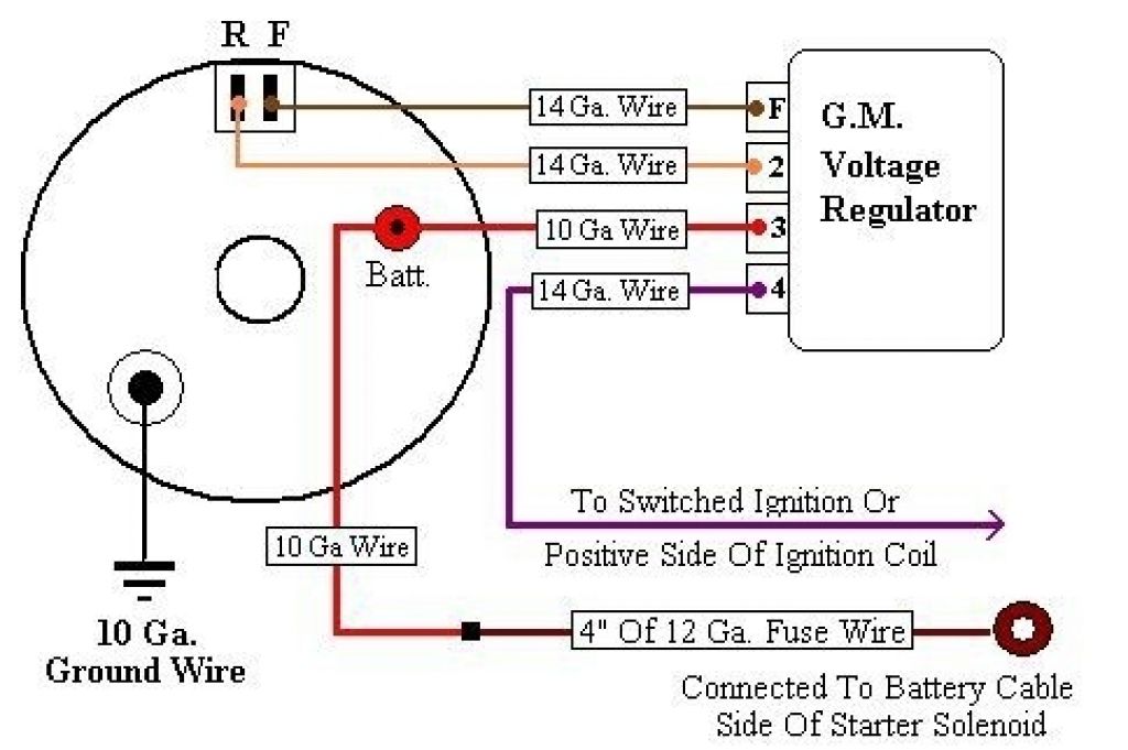
- Rectangles with wavy lines: Often represent the voltage regulator. Look for labels like "FLD" (field), "IGN" (ignition), "BAT" (battery), and "GND" (ground) to identify the terminals.
- Alternator Symbol: Typically a circle with a three-phase winding symbol inside. It will also have terminals labeled for field ("F"), stator ("S"), and battery ("B").
- Ground Symbol: Usually a series of downward-pointing triangles, indicating a connection to the vehicle's chassis (ground).
- Resistor Symbol: A zigzag line, representing a resistor used to limit current flow.
- Capacitor Symbol: Two parallel lines, representing a capacitor used to store electrical energy.
- Color Codes: Wires are often color-coded to aid in identification. The diagram will typically have a legend explaining the color codes (e.g., "Red = Battery," "Black = Ground," "Blue = Ignition").
How It Works: A Step-by-Step Explanation
Okay, let's get into the nitty-gritty of how this system operates.
- Starting Up: When you turn the ignition key, a small current flows from the battery, through the ignition switch, and to the voltage regulator (typically labeled "IGN"). This wakes up the regulator.
- Field Excitation: The regulator then allows a controlled current to flow to the alternator's field winding (rotor). This creates a magnetic field inside the alternator.
- Generating Power: As the engine turns the alternator's rotor (via the belt), the rotating magnetic field induces a voltage in the stator windings (the stationary coils).
- Rectification: The AC voltage produced by the stator windings is converted to DC voltage by diodes within the alternator.
- Voltage Regulation: The voltage regulator continuously monitors the battery voltage (typically via a "BAT" terminal). If the voltage is too low, the regulator increases the current flowing to the field winding, boosting the alternator's output. If the voltage is too high, the regulator reduces the field current, decreasing the alternator's output.
- Charging the Battery: The DC voltage from the alternator (typically 13.8-14.7V) is then used to charge the battery and power the vehicle's electrical accessories.
- Feedback Loop: The regulator constantly adjusts the field current to maintain the desired voltage, creating a closed-loop feedback system.
Real-World Use: Basic Troubleshooting Tips
Let's say your battery light is on. What do you do? Here's a basic troubleshooting approach using the wiring diagram:
- Visual Inspection: Check all wiring connections for corrosion, looseness, or damage. Pay close attention to the connections at the alternator, voltage regulator, and battery terminals.
- Voltage Checks: Use a multimeter to measure the voltage at the battery terminals with the engine running. It should be between 13.8V and 14.7V. If it's significantly lower (e.g., 12V or less), the alternator may not be charging.
- Field Wire Check: With the engine running, check the voltage at the field wire terminal on the alternator. It should be less than battery voltage. If the field has full battery voltage, the regulator may be bad.
- Ground Connections: Ensure the alternator and voltage regulator have good ground connections to the vehicle's chassis. A bad ground can cause all sorts of problems. Clean the ground points with a wire brush or sandpaper.
- Fuse Check: Inspect the fuses or fusible links in the charging circuit. Replace any blown fuses with the correct amperage rating.
- Regulator Test: Many auto parts stores can test your voltage regulator to see if it's functioning properly.
- Alternator Test: Likewise, you can take your alternator to most auto parts stores to have it tested.
Safety: Handle with Care!
Working with electrical systems can be dangerous. Here are some key safety precautions:
- Disconnect the Battery: Always disconnect the negative battery cable before working on the charging system to prevent short circuits.
- Avoid Shorts: Be careful not to short circuit any wires to ground. This can damage components and create a fire hazard.
- Wear Eye Protection: Wear safety glasses to protect your eyes from sparks or debris.
- Work in a Well-Ventilated Area: If you're working with batteries, make sure the area is well-ventilated to prevent the buildup of explosive hydrogen gas.
- Identify High Current Wires: Be especially cautious of the battery cable and the wires connected to the alternator's battery terminal. These carry high currents and can deliver a serious shock.
With this understanding of the external regulator wiring diagram, you're well-equipped to diagnose and repair charging system issues. Remember to take your time, be careful, and consult the specific wiring diagram for your vehicle. It's your best friend in this electrical endeavor!
We have a detailed wiring diagram file available for download to help you further in your project. It includes color-coded wires, component locations, and detailed specifications.